
Overview
Decarbonisation of District Heating: Transforming the Heating Plant in Three Steps
The decarbonisation of district heating is the key strategy that German utilities are employing to achieve greenhouse-gas neutrality in their district and local heating networks by 2045. Rather than switching off existing combined heat and power (CHP) plants, the focus is on combining them with large-scale heat pumps to create hybrid, grid-serving heating plants that are controlled according to electricity price signals. This article explains where heating plants are used, the role of municipal heat planning, the criteria for considering a heating plant “decarbonised”, and the three-step process of this transformation in district heating system design.
Table of contents
- Where are heating plants used in district heating?
- When can we say that a heating plant has been decarbonised?
- What’s the difference between a district heating decarbonisation plan and a heating plant decarbonisation?
- What does sector coupling mean for the decarbonisation of heating plants?
- What does a typical heating plant decarbonisation look like in three steps?
- Practical examples of decarbonising heating plants
- The role of system design, simulation and control in heating plant decarbonisation
- Frequently Asked questions
Where are heating plants used in district heating?
Heating plants, also known as heating centers, are central generation sites for piped heat supply. They can be found in everything from single multi-family housing developments to large urban district heating and cooling systems.
On the smaller scale, there is the heating plant of a multi-family housing development or neighbourhood, where a single plant room supplies a few to several dozen buildings via a local heating network. This is often operated by a utility or energy service provider under a contracting solution. At the other end of the scale are large district heating plants that supply entire districts or cities with several hundred megawatts of connected capacity. These plants are linked to residential, commercial, and industrial areas through branched transport networks. In between are local networks for commercial areas, hospital and university campuses, and mixed-use new developments.
The key difference between local and district heating lies less in a fixed capacity threshold than in network extent, connection density, and operating model . The boundaries are fluid. This is important for decarbonisation because large heat pump cascades and CHP-booster concepts can be scaled up or down technically: the logic of a base-load heat pump plus a grid-serving CHP unit applies equally to heat pump district heating and full district heating.
When can we say that a heating plant has been decarbonised?
A heating plant is considered to be undergoing decarbonisation when an existing fossil-dominated plant is gradually converted to run on renewable heat sources and flexible, grid-serving generation, without interrupting the heat network or compromising security of supply.
This term is deliberately distinct from new-build projects. It is not about creating a ‘green heat network on a greenfield site’, but rather about rebuilding an existing asset while it remains operational. The fossil peak-load boiler is retired, the CHP unit continues to operate but in a different way, and a new large heat pump or heat pump cascade progressively takes over the base load. Another characteristic of decarbonisation is that it happens in stages, from a fossil-dominated starting system through a hybrid transition system to a fully decarbonised target system. This is typically aligned with the legally anchored target year of 2045.
What’s the difference between a district heating decarbonisation plan and a heating plant decarbonisation?
At first glance, the two terms sound similar, but they describe two distinct, closely related planning levels: the strategic direction of the entire district heating network on the one hand, and the technical implementation at the individual plant on the other.
District heating decarbonisation plan
The district heating decarbonisation plan operates at a strategic municipal level. In Germany, this is anchored in law through the Heat Planning Act (Wärmeplanungsgesetz, WPG, 2024). It addresses how a city or municipality’s heat network will evolve over the next 10 to 30 years. It is usually produced by utilities, energy suppliers or municipalities, often with the help of external consultants. Further details on this planning process can be found in the companion article on district heating decarbonisation planning.
Heating plant decarbonisation
By contrast, heating plant decarbonisation operates at a technical and operational level, addressing how the specific plant that currently generates heat can be converted to renewable or hybrid generation. This includes:
- Replacing or supplementing the existing boiler (gas, oil, coal) with heat pumps, CHP, solar thermal or waste heat
- Hydraulic redesign: how new generators are integrated into the existing network
- Control strategy: which unit takes precedence at any given time (heat pump, CHP or peak-load boiler)
- Storage integration: how a buffer or seasonal storage tank is sized
- Network temperature adjustment: whether the supply temperature can be lowered without compromising security of supply
- Monitoring and digital twin: how the new operating regime is supervised
This work is usually carried out by utility companies, building services engineers, planning engineers or contractors.
The district heating decarbonisation plan provides the direction, while heating plant decarbonisation delivers it technically. In practice, the two are closely intertwined. For example, the decarbonisation plan may set a target of reducing the network temperature to 70 °C by 2035, in which case the heating plant would need to be redesigned to meet this target while ensuring security of supply.
| District heating decarbonisation plan | Heating plant decarbonisation | |
| Level | Strategic / municipal | Technical / plant-specific |
| Time horizon | 10–30 years | 2–5 years (project) |
| Actors | Utility, municipality | Utility, planner, contractor, operator |
| Output | Master plan, investment plan | Detailed design, simulation |
| Regulatory framework | see country coparison below | DE: EnEfG, GEG; CH: SIA 384 |
| Role of Polysun | Scenario comparison, potential analysis | Hourly annual simulation |
The regulation of district heating varies across Europe. The table below provides an overview of the main legal framework in several countries that have significant district heating markets.
| Germany | Heat Planning Act (Wärmeplanungsgesetz, WPG, 2024); Building Energy Act (GEG) | Municipalities (heat planning); BAFA (funding) |
| Switzerland | Cantonal heat planning (Energierichtplan); SIA 384 standards | Cantons; BFE (Wärmestrategie 2050) |
| United Kingdom | Energy Act 2023; Heat Networks (Market Framework) (Great Britain) Regulations 2025; Heat Network Zoning | Ofgem (regulator, in force since January 2026) |
| Sweden | District Heating Act (Fjärrvärmelagen 2008:263) | District Heating Board (Fjärrvärmenämnden) for mediation; pricing remains market-based |
| Norway | Energy Act (Energiloven), including provisions on district heating | NVE (Norwegian Water Resources and Energy Directorate) – concessions, connection and price regulation |
| Netherlands | Collective Heat Act (Wet collectieve warmte, Wcw), replacing the Heat Act (Warmtewet), expected to enter into force in 2027 | ACM (Netherlands Authority for Consumers and Markets) |
Note: several of these frameworks – notably the UK and Dutch regimes – are still being phased in as of 2026 and subject to change; the table above reflects the status at the time of writing.
What does sector coupling mean for the decarbonisation of heating plants?
It means that the power and heat sectors are technically and economically interlinked, enabling generators and consumers to react flexibly to the cheapest or scarcest energy source at any given moment rather than operating in isolation.
In a heating plant, this is evident in the form of a heat pump cascade, which is typically designed for supply temperatures ranging from 80 to 110 °C. This cascade covers the base load and draws electricity from the public grid. When cheap wind or solar power is abundant on the energy exchange market, the heat pump cascade uses that electricity and the combined heat and power (CHP) unit stands idle. When electricity prices rise due to scarce wind and sunlight, the CHP unit starts up and generates highly efficient electricity for the heat pump cascade. It also simultaneously feeds its own waste heat directly into the network. The CHP unit thus transforms from a pure base-load generator into a ‘CHP booster’ that provides power precisely when the system requires it. This interaction — where electricity provides heat and relieves the power grid — is the core of sector coupling in heating plants and the reason why the concept is attractive from both a climate and an economic policy point of view.
What does a typical heating plant decarbonisation look like in three steps?
The process involves three consecutive stages: transitioning from a fossil legacy system to a hybrid system and finally to a greenhouse-gas-neutral system by 2045.
Stage 1 – the fossil legacy system
The natural gas CHP unit primarily generates electricity or heat and covers the base load, while a fossil gas peak-load boiler kicks in during extreme cold spells in winter. The main disadvantage of this stage is the high CO₂ emissions from the peak-load boiler and the lack of flexibility in summer when the CHP unit is often completely shut down due to a lack of demand for heat.
Stage 2 – the hybrid transition system
The CHP unit switches to grid-serving operation while a heat pump cascade, fed by air, wastewater or surface water, takes over the base load. When exchange electricity prices are high, the CHP unit generates power to drive the heat pump cascade directly, and the CHP engine’s waste heat and the heat pump’s output flow together into a large thermal buffer store. Consequently, the fossil fuel-powered peak-load boiler only fires in exceptional cases and the CO₂ balance improves dramatically. This is the stage at which heat pump district heating and CHP converge to form a single, jointly controlled system.
Stage 3 – the target system
While the operating principle remains the same, the energy carriers are fully decarbonised. The CHP unit burns green hydrogen or synthetic methane, and large-scale heat pumps utilise deep geothermal energy or river water as a constant, highly efficient heat source, resulting in a strong coefficient of performance (COP). Solar thermal collectors are often added to many networks as an additional renewable source, either feeding the buffer store directly or pre-heating the return flow to increase the efficiency of the heat pump – a combination sometimes referred to as solar district heating. The result is emission-free district heating that acts as a highly flexible power-to-heat-to-power battery for the electricity grid.
| Legacy system | Transition system | Target system | |
| Base load | Fossil gas CHP | heat pump cascade | Large-scale heat pumps (ambient/geothermal energy) |
| Peak load | Fossil gas boiler | Grid-serving CHP | H₂-CHP |
| Storage | Barely present | Thermal buffer storage | Large-scale, seasonal storage |
| Flexibility | Low | High | Very high |
Practical examples of decarbonising heating plants
Heating plant decarbonisation for a residential development in the Ore Mountains (Erzgebirge)
A residential development in the Ore Mountains (Erzgebirge) in Germany, comprising five multi-family buildings, was until recently heated by five separate building-level gas boilers. As the boilers reached the end of their useful life and gas prices were rising, the owner had to make a fundamental decision: should they replace the individual fossil fuel supply with decentralised heat pumps on a one-to-one basis, or invest in a networked solution that would offer better long-term economics and operations?
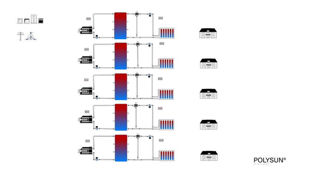
To make an informed decision, three system variants were compared through simulation and evaluated based on investment cost, operating cost, and seasonal performance factor.
| Variant | Network type | Description | Assessment |
| A – Centralised, high-temperature | Networked | Central heat pump, network at 60 °C supply temperature | Higher network losses due to the high temperature level, correspondingly higher heat pump electricity consumption |
| B – Decentralised air-source heat pumps | Decentralised | Each building gets its own air-to-water heat pump | Lowest investment cost, but higher maintenance effort across five separate units and higher total electricity consumption than Variant C |
| C – Cold local heating network | Networked + decentralised boosters | Central brine-to-water heat pump feeds an anergy network, with temperature boosted building by building | Higher investment cost, but the lowest electricity consumption and the best long-term economics |
The simulation showed that, although Variant C requires a higher upfront investment, this pays off during operation because the network itself runs at only 10 to 15 °C, resulting in practically negligible distribution losses. By contrast, Variant A sees both transmission losses and heat pump electricity demand rise due to the high network temperature. Compared with the purely decentralised solution (Variant B), Variant C is more economical and has a better CO₂ balance thanks to a single, centrally maintained generation unit instead of five separate systems.
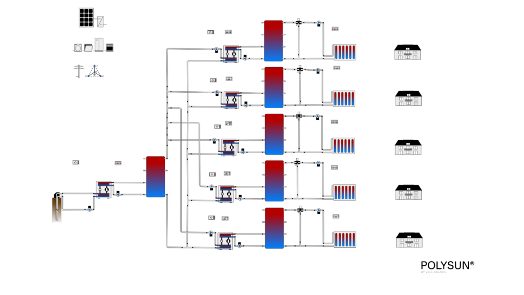
The chosen solution (Variant C) is a local low-temperature heating network, also know as Anergie Network. This connects the five buildings, with temperatures in the network ranging from 10 to 15 °C. A central brine-to-water heat pump, fed by 16 borehole heat exchangers, charges a central buffer store. In each building, a compact, decentralised water-to-water heat pump raises the temperature to 55 °C for space heating. A newly installed photovoltaic (PV) system covers part of the heat pumps’ electricity demand, further improving operating economics.
This example illustrates why considering generation-equipment costs alone is insufficient for decarbonising a heating plant: only a simulation-based analysis of network losses, heat pump electricity consumption, and operating costs over a full year reveals the most economical variant.
Heating plant decarbonisation for a district heating network – example from Saxony-Anhalt
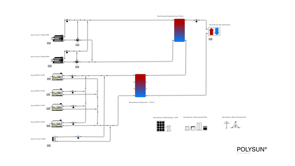
Existing plant. In Saxony-Anhalt, a district heating plant is being decarbonised. The plant has been continuously expanded and currently comprises two gas boilers (2 × 8 MW) and four combined heat and power (CHP) units (4 × 1.3 MWth), which together cover a peak heat load of 12 MW. Currently, the gas boiler covers peak demand while the CHP units carry the base load – a classic setup that is still largely fossil-dominated ahead of the heating plant’s decarbonisation.
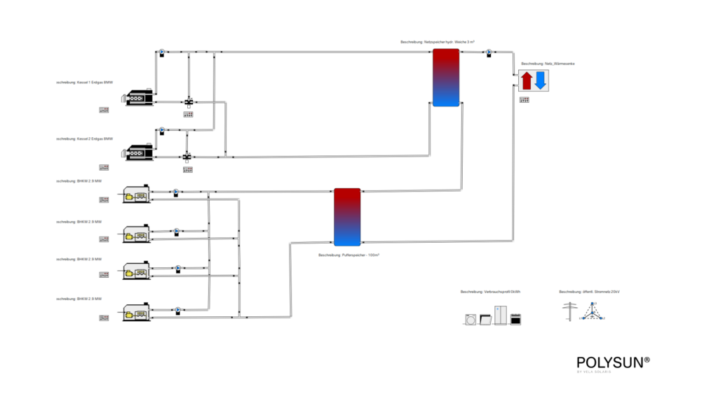
Decarbonisation step 1: adding power-to-heat and wind power
The existing plant is first expanded into a hybrid heating plant by adding a 15 MW electric boiler to the existing generators. This boiler converts electricity directly into heat as needed. This electricity will be supplied by a planned wind turbine. An overarching control system ensures that electricity is only converted into heat when market conditions make it economically viable to do so, for example during periods of low or negative electricity prices.
Decarbonisation step 2: integrating a solar thermal array
In the final step, a solar thermal field will be integrated into the hybrid heating plant. As solar thermal has the lowest marginal cost of any generator in the system, it is prioritised in the control logic and supplies heat whenever it is available. Depending on the current electricity market price, the electric boiler, CHP units or, as a last resort, the gas boiler are dispatched in turn. At its core, this cost-based generator ranking is an ongoing comparison of the levelised cost of heat per generator: the unit that can deliver heat most cheaply covers the load first.
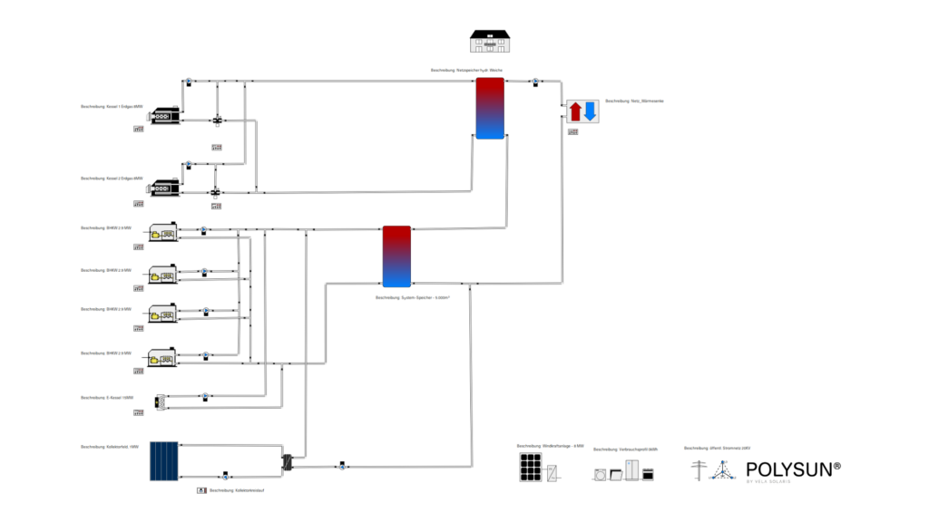
The example from Saxony-Anhalt illustrates a different aspect of district heating system design to the residential development case mentioned above. Rather than using a heat pump cascade, this hybrid heating plant is based on a combination of power-to-heat, wind power and solar district heating. These are dispatched according to the same underlying principle of cost-optimised generator merit order.
The role of system design, simulation and control in heating plant decarbonisation
Plant simulation enables the intended decarbonisation steps of a heating plant to be planned reliably. For example, it can reveal whether a hybrid heating plant with a planned combination of a large heat pump and a CHP unit would be able to reliably supply the network even on the coldest winter day. Expensive planning errors can be avoided and optimisation potential can be identified that would never be revealed by a purely spreadsheet-based calculation – both of which are central to sound district heating system design.
Tools such as Polysun physically and modularly model heating plants: CHP units, heat pump cascades and buffer stores can be connected hydraulically via drag-and-drop, and heat pump COP values are dynamically interpolated based on source and supply temperature, regardless of whether the source is ambient air, a geothermal field or a solar thermal loop. The key is the time-step simulation across a full year based on real weather data and load profiles, as this is the only way to verify whether the heat pump can deliver the required supply temperature in January with an outdoor air temperature of minus 10 °C.
A second key building block is the control logic. The simulation software is configured with rules such as the following: if the temperature of the buffer store in a given layer drops below a defined threshold and the electricity price exceeds a defined level simultaneously, the CHP unit switches on and feeds power into the heat pump cascade. If the electricity price is negative, the CHP unit remains off and the heat pump runs entirely on grid electricity. This combination of physical simulation and economic control logic also offers a tangible advantage in terms of sizing: a well-designed buffer store can often reduce heat pump capacity by 20 to 30 percent – providing a direct solution to the tendency of utilities to oversize for safety reasons. Furthermore, simulation reports from such tools are widely accepted by banks and funding bodies as valid evidence of the technical and economic feasibility of decarbonisation projects.
Scenario comparison also enables ‘what if’ analyses for the target year of 2045. For example, it is possible to compare heat pump district heating with geothermal district heating as the long-term base-load source or test how a solar thermal array would affect the heat pump’s seasonal performance factor. This increases the future-proofing of these systems and minimises planning risk.
Frequently Asked questions
Can levelised cost of heat per variant be simulated under dynamic electricity prices?
Yes. Modern simulation software can calculate levelised cost of heat (LCOH) for several network variants in parallel while factoring in real, time-resolved electricity price series such as day-ahead exchange data. This makes it possible to compare a heat pump district heating variant that buys grid electricity flexibly against a CHP-led variant, or a geothermal district heating base load against a purely air-source heat pump base load, on a genuinely like-for-like operating-cost basis rather than on static annual averages.
Can the control of multiple generators under dynamic electricity prices be optimised with AI?
Yes, artificial intelligence is already being used in several district heating networks to improve load forecasting and automatically optimise the generator mix of CHP, heat pump and storage under dynamic electricity prices. A machine-learning-based heat load forecast can materially reduce forecast error compared with classical methods; on that more accurate data basis, an optimisation function then calculates the most cost-effective generator mix for the period ahead – complementing, rather than replacing, the rule-based control logic used for day-to-day operation.
From how many buildings does a networked system pay off compared with decentralised heat pumps?
There is no fixed building count that serves as a threshold – economics depend far more on building density, heat demand structure and locally available heat sources than on the number of buildings alone. In practice, the closer buildings sit together and the more heterogeneous their refurbishment status, the more a centralised or cold local heating network tends to pay off, because generation, maintenance and peak-load coverage can be pooled. For widely spaced individual buildings with low connection density, network costs rise disproportionately, so decentralised single-building heat pumps often remain the more economical choice. This threshold can only be determined reliably through simulation-based scenario comparison that sets network losses, investment cost and operating cost against the actual building layout – rules of thumb tend to produce wrong calls in both directions.
How is the remaining service life of existing generators such as CHP units or boilers factored into decarbonisation planning?
Existing generators with meaningful remaining service life are typically not replaced immediately, but integrated into the new hybrid operating concept for as long as technically sensible – for example as a grid-serving peak-load or booster unit, while a new large heat pump takes over the base load. This reduces the initial investment and avoids decommissioning still-functional assets. Simulation can model this staged approach directly: the existing unit is entered into the model with its real performance curves and planned remaining runtime, so the transition to the next expansion stage can be planned precisely in both timing and economics – including the point at which early replacement pays off despite remaining service life, for instance due to sharply rising fuel costs or falling spare-part availability.