Reversible Heat Pump: Heating and Cooling with a Single Unit
A reversible heat pump meets both the heating and cooling needs of a building with a single unit. In the winter, it operates as a heat pump; in the summer, it reverses the refrigeration cycle and operates as a chiller. This allows space heating, hot water, and building cooling to be combined in a single hydraulic system.
This article describes the simulation of a reversible heat pump in Polysun. The underlying computational model corresponds to the standard model of an air-to-water heat pump. Both operating modes—heating and cooling—were defined within the same component and switched between during the simulation.
Modeling the Reversible Heat Pump
The reversible heat pump is depicted as a component with two hydraulic connections. For both operating modes, Polysun uses the same interpolation method as for the air-to-water heat pump: Based on measured data points for output and power consumption, the current thermal output and electrical power consumption are interpolated for each time step.
- Heating mode: The selected heat source (outdoor air, brine, or water) serves as the heat source; the condenser supplies the load or storage circuit. The reference point is A7/W35; efficiency is reported as COP.
- Cooling mode: The thermodynamic cycle is reversed. The load circuit is now cooled via the evaporator, and the heat extracted is transferred to the selected source—now acting as a heat sink. The reference point is A35/W18, and efficiency is reported as EER.
Select operation mode: Heating, Cooling, or Reversible
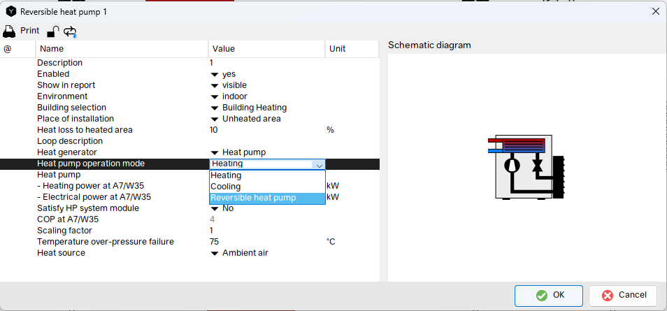
In the heat pump’s component dialog box, use the “Heat pump operation mode” selection to specify how the unit will operate:
- Heating – the heat pump generates heat exclusively.
- Cooling – the heat pump operates exclusively as a chiller.
- Reversible heat pump – the unit can operate in both modes; the mode is switched during the simulation.
For a reversible system, select “Reversible Heat Pump.”
Switching Between Heating and Cooling Modes
The programmable controller uses the “Operation Mode” output to determine which operating mode is active at any given time:
| Operation mode | Control value |
|---|---|
| Heizen | 1 |
| Kühlen | 2 |
Typically, the operating mode is set based on the season, the outdoor temperature, or the building’s current heating or cooling demand. The configuration of the control outputs is described in the chapter “Programmable Controller.”
Note: The “operating mode” of the reversible heat pump is independent of the “control mode” of the modulating air-to-water heat pump (heat-controlled, power-controlled, defined power level). It determines only the direction of the refrigeration circuit. If no operating mode is set, the heat pump remains in heating mode.
Catalog entry for the reversible heat pump
Reversible heat pumps listed in the catalog include performance data for both operating modes. The most important fields:
| Field | Meaning |
|---|---|
| Heating power at A7/W35 | Thermal heating power at the reference point |
| Electrical power at A7/W35 | Electrical power in heating mode at the reference point |
| Cooling power at A35/W18 | Cooling power at the reference point |
| Electrical cooling power at A35/W18 | Electrical power in cooling mode at the reference point |
| COP at A7/W35 | Coefficient of performance in heating mode |
| EER at A35/W18 | Coefficient of performance in cooling mode |
| Scaling factor | Factor for scaling all performance data (e.g., for parallel devices) |
| Temperature over-pressure failure | Condenser outlet temperature above which the heat pump shuts down in heating mode (high-pressure shutdown) |
| Low pressure fault (load loop, cooling) | Minimum flow temperature in the load circuit during cooling mode; if the temperature falls below this level, the heat pump shuts off. |
| Heat source | Heat source or sink: outdoor air, brine, or water |
In addition, the component dialog box includes the placement fields “Environment” (outdoor/indoor), “Place of installation,” and “Heat Loss to heated area”—similar to the air-to-water heat pump.
Support points from profile files
As with other types of heat pumps, the support points can either be entered directly into the catalog fields or imported from a profile file. The file must be located in the “profiles” folder within the Polysun data directory and be in “csv” format.
The reversible heat pump uses two separate profile files:
- one profile file for the heating mode,
- one profile file for the cooling mode,
Both files have the same structure as the profile file for the air-to-water heat pump. The heating profile file contains the heating capacity, and the cooling profile file contains the cooling capacity; the reference point for the cooling data is A35/W18.
Structure of the heating profile file:
#Name of the heat pump;;;;
#Evaporator[°C];Condenser[°C];HeatingPower[W];ElectricalPower[W]

20;35;20800;4100
10;35;18700;4100
…
In heating mode, “evaporator” corresponds to the temperature of the heat source (e.g., outdoor air), and “condenser” corresponds to the flow temperature of the load circuit. In cooling mode, the assignment of temperature levels is reversed: “Evaporator” then refers to the (cold) flow temperature of the cooling circuit, and “Condenser” refers to the temperature of the heat sink (e.g., outside air).
The same formatting rules apply as for the air/water heat pump (separator “;”, all headers preceded by “#”, no rows with missing values, no duplicate data points).
Notes on Calculation and Simulation
- Switching via the controller only: The reversible heat pump changes its operating mode exclusively via the controller’s “Operating Mode” output (1 = Heating, 2 = Cooling).
- Heat source becomes a heat sink: In cooling mode, the heat pump transfers the heat extracted from the building to the source selected in the catalog. This additional heat input must be taken into account when designing the source (e.g., ground probes).
- High-pressure fault: If the condenser outlet temperature exceeds the “High-pressure fault temperature” value, the heat pump shuts down in heating mode.
- Low-pressure fault (load circuit, cooling): If the flow temperature in the load circuit falls below the stored value, the heat pump shuts down in cooling mode. This prevents icing or condensate formation.
- Modulation in cooling mode: The modulation types “None” and “As needed” are available for cooling mode.
- Start-up losses are not taken into account—as in the standard model.
Simulation Results
In the component’s results overview, heating and cooling modes are shown separately:
| Description | Symbol | Unit | Meaning |
|---|---|---|---|
| Energy from/to the system | Qaux | MWh | Heating energy supplied to the system |
| Cooling energy from/to the system | Qaux_cooling | MWh | Cooling energy removed from the system (negative sign) |
| Fuel and electricity consumption | Eaux | kWh | Electricity Consumption (Heating and Cooling) |
| Coefficient of Performance | COP | – | Annual Coefficient of Performance in heating mode |
| Energy Efficiency Ratio (cooling) | EER | – | Annual Coefficient of Performance in cooling mode |
| On/Off | % | – | Average performance level |
| Operation time | h | – | Operation time |
| Number of switch-on times | – | – | Number of compressor starts |
In the results overview for the variant, the cooling energy is also displayed as “Supplied cooling energy” (Qaux_cooling).
Templates
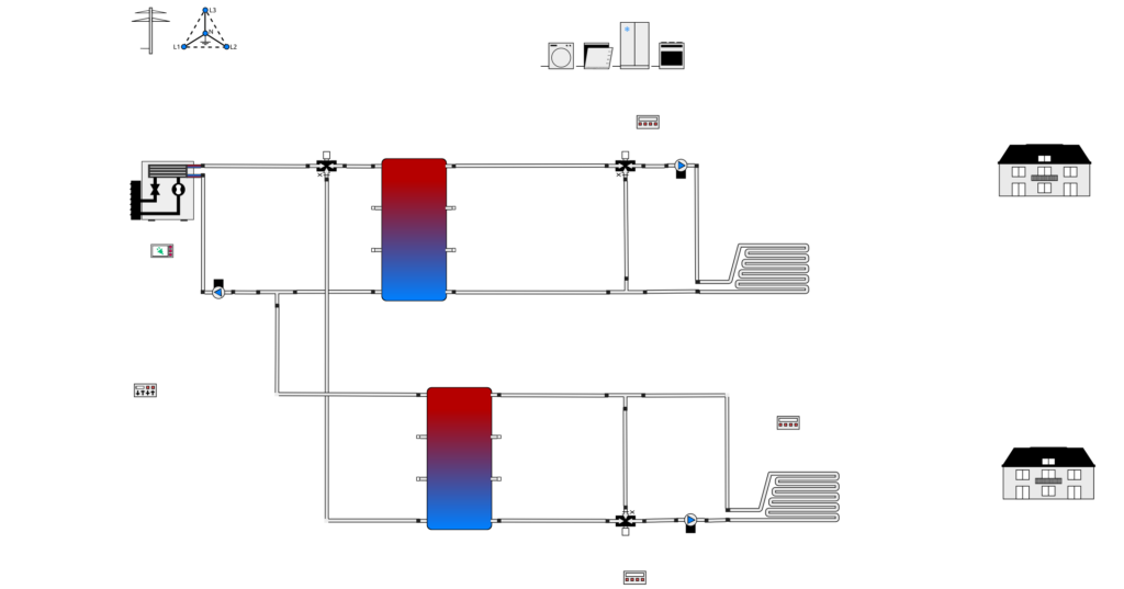
This standard template is available for the design of reversible heat pump systems: “Variant 70 m: Reversible air-to-water heat pump with buffer tank and cold storage tank.” The reversible heat pump supplies a heating circuit with a buffer tank and a cooling circuit—separated from the heating circuit by the operating mode switch and two 3-way valves—with a cold storage tank. The heating and cooling circuits are each connected to an apartment building via their own manifold with a circulation pump.