
Modeling of Pipe Heat Losses for Energy System Design
In Polysun, pipes form the basis for a realistic hydraulic model of the transfer circuit. Using the pipe parameters, Polysun calculates losses in the pipes under different temperature conditions. The precise selection of pipes influences the system’s performance and efficiency throughout the year. In Polysun, you can adjust pipe parameters and compare scenarios.
Adjusting Pipe Parameters Throughout the System
The dimensions of an individual pipe can be adjusted by double-clicking on the desired pipe. This allows any parameters – such as diameter, length, resistance coefficient, thermal insulation, and insulation thickness – to be changed. The type of pipe, including diameter, can be selected via the pipe catalog. In addition, the installation location of the pipe can be defined.
Important: The pipe dimensions affect the simulation speed. If pipes are undersized, this leads to longer simulation times.
To adjust multiple pipes with the same dimensions more quickly in a system, the pipe selection tool can be used. This is located at the top of the pipe adjustment window.
In the pipe selection tool, all pipes that should have the same dimensions can be selected. All pipes can be selected directly using the “Select all” checkbox. The pipes are grouped into the logical circuits within the system, for example “Pump 1.” This allows related pipes to be assigned the same parameters more quickly. The middle mouse button can be used to pan the background so that the numbering of the desired pipes becomes visible. After the pipe selection, another pipe adjustment window opens based on the previous selection. The window title shows how many pipes are currently being edited.
If only certain pipes need to be adjusted, these pipes can be selected using a drag selection, and the “Edit pipe parameters” function can be called up by right-clicking on a pipe.
This opens the pipe selection tool, where the selection can be reviewed and the pipe adjustment carried out.
Determining the Diameter of Pipes
To define the thickness of the pipes the following aspects are to be considered:
- Pipes with a large diameter have a large surface area and therefore greater heat loss
- Pipes with a large internal diameter allow for a higher flow rate
- In thicker pipes the fluid flow is laminar, something which slows the transverse heat transfer in the fluid and causes lower heat losses
- Thicker pipes (equal in length) have a greater volume, which presupposes a greater quantity of heat transfer fluid in the collector loop and makes the system inert.
From these considerations it can be concluded that the pipe diameter should generally be kept small, and is essentially determined by the criterion of an appropriate pressure loss.
Pipe diameter and wall thickness are given by a catalog of commercially available pipes (made of copper and steel). For copper pipes, the specification 22 x 1 means an outer diameter of 22 mm and a wall thickness of 1 mm. For gas pipes, the inner diameter is given in inches (1 inch = 2.54 cm).
Heating pipes insulation
Thermal insulation of the piping is very important. Good insulation materials of an appropriate thickness of a few centimeters ensure acceptable heat losses.
The thickness of the thermal insulation, as well as its thermal conductivity, can be freely defined. Also decisive for the thermal behavior of the pipes are the thermal conductivity and heat capacity of the metal pipes used. The total pipe length can be specified separately in the corresponding fields. It is important to also take into account details such as the length of the pipe run indoors versus the length of the pipe run outdoors in the simulation. To do this, two separate pipes are set up, whose insulation thickness and length can then be entered separately.
Pipe Dimensions
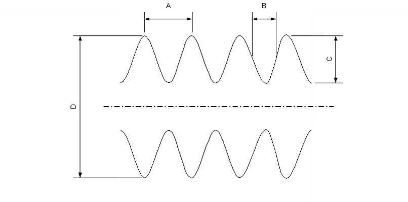
Simulation of Pipe Losses
Especially in heating networks, thermal pipe losses due to underground installation and long distances are not negligible. For a realistic simulation of these pipe losses, the pipe parameters (diameter, insulation thickness, and length) must primarily be adapted to match the real system.
Once the pipe dimensions are correct, the pipes of the distribution network can be included in the heating network by marking the desired pipes with a drag selection and calling up the “Edit pipe parameters” function by right-clicking on a pipe. The “Part of the heating network” setting must be set to “Yes” so that the selected pipes are taken into account in the heat loss calculation.
Once the pipes have been included in the heating network, the heat losses of the pipes can be viewed in the system results under the category “Heat losses of the heating network (QhlGrid).” The heat losses are output both monthly and annually.
Heat Transfer Fluids
The climatic conditions in central Europe make it necessary for solar energy systems to be resistant to temperatures below zero. This, for example, impedes the production of necessary hot water directly in the collector. When water freezes inside the collector, it destroys the collector by means of its expansion. The water of the hydro network furthermore has the disadvantage that it tends to calcify the collector over time.
In order for the heat transfer fluid to be suitable for the above-mentioned needs, water is mixed with a certain quantity of glycol. In many cases ethylene glycol is used as an anti-freeze (for example Antifrogen L) or propylene glycol (e.g. Antifrogen N). From the moment the fluid circulates in a closed circuit, the danger of calcification is contained. For the mixing proportions the following various points of view are to be considered:
- The heat capacity of the fluid diminishes with an increased concentration of glycol
- Viscosity increases with higher percentages of glycol (problems with pressure loss)
- The freezing point drops with an increase in the percentage of glycol
- The boiling point increases with higher percentages of glycol
- Different possible chemical processes must be kept in mind, especially in passing through different metals
- The heat resistance of the fluid is to be considered
Freezing fluid is no longer a problem starting from a certain concentration as it no longer freezes as ice (crystalline), but rather in a grainy gelatinous form. Explosive effects are no longer evident. Beginning with a volumetric percentage of 33% (propylene glycol), or 38% (ethylene glycol), the fore-mentioned results take effect.
In Polysun the concentration of glycol can be defined. The corresponding physical properties for a temperature of 50°C are indicated.
Heat Transfer Media (Mix of Fluids)
- Danger of freezing in winter: if we consider that the external temperature can reach below zero, an anti-freeze product would be used (normally glycol). The higher the quantity of glycol, the lower the thermal capacity of the fluid. Ethylene glycol is normally used at a concentration of 33% (propylene glycol at 38%). In this way the fluid only freezes “like gelatin” without causing explosive effects inside the collector.
- Calcification of the system: for this condition there are two aspects to consider: if pipes with a small internal diameter are used inside the collector, calcification may obstruct the collector over time. Calcification may become a problem also in the tank. The situation is further aggravated if water is brought to temperatures above 60°C.
- Sterility of the tank: if domestic hot water is ready for use in the tank, there is a possible risk of legionella bacteria. This can be avoided by periodically heating the tank to above 65°C. In domestic hot water systems with an annual degree of coverage above 50%, sterility in summer is guaranteed by the temperature of the season.
For the choice of the system, cost considerations naturally also come into play. External heat exchangers are normally more expensive than internal ones, they require an auxiliary pump, but have greater transfer efficiency than internal heat exchangers. External heat exchangers are used above all in large systems, where the higher expense is compensated by greater efficiency.
What is the role of pipes in energy system design?
Pipes transport heat transfer fluid between components, such as collectors and tanks, with minimal heat loss. In Polysun, pipes are modeled to optimize system efficiency by balancing heat loss and fluid volume.
Is Polysun a Pipe Heat Loss Calculator?
Polysun isn’t just a Pipe Heat Loss Calculator; it’s a comprehensive energy system simulation tool that includes pipe heat loss calculations. It models pipes by factoring in diameter, material, insulation, and fluid properties to optimize efficiency.
How does Polysun handle pipe insulation for indoor vs. outdoor piping?
Polysun allows users to model indoor and outdoor piping separately, enabling them to specify different insulation thicknesses, lengths, and materials for each. Furthermore, the heat loss calculation takes weather data into account, enabling precise results.