General Control Features
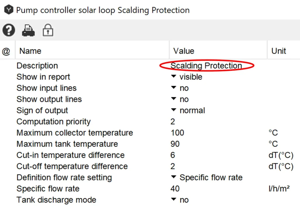
Controller “Description“
Entering figures or text in the field “Description“, these will appear after closing and re-opening the window in the title area of the controller:
Automatic Numbering of Polysun:
Adding multiple controllers in Polysun this latter will automatically assign each controller a consecutive number regardless of the fact that previously added controllers were later cancelled. Such consecutive numbers may be edited manually. A resetting of the consecutive numbering is, however, impossible. For each new system diagram the numbering will automatically start from ”1“.
Timer Controller
The “timer function“ may be used for all controllers, i.e the user will be able to define availability times in which the controller should be operating. This function enables to enter time, day and month in which the controller should be ”active“ as required. In idle mode outputs are set to zero.
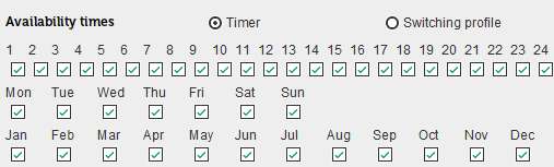
The definition of independent ”week and month profiles“ is not possible.
Controller Outputs
Two parallel outputs are usually available. If two components need to be switched on and off in parallel this may be achieved by means of a special controller. In case of a number of parallel controlled components in excess of two the controller should be copied. An exception is provided by the mixing valve controller that only outputs an analogic signal.
“Energy Demand Not Covered”
A number of controllers (e.g.: temperature, flow rate) allow to set fixed and variable temperature settings. Sometimes after running a simulation the energy demand will be shown as ”not covered“. This may happen if the temperature settings or flow rates defined within controllers and user profiles are not reached.
You may, for example, have set a mixing valve controller to ”variable temperature setting: hot water demand“ and entered in the hot water user profile a temperature of 50°C. If the controller was set so that the temperature setting for hot water may not be reached (e.g. due to temperature losses between mixing valve and tap) Polysun will show the report “Energy demand not covered” once the simulation is over. If this is the case check the state of the different temperature levels and compensate the temperatures in the controllers by means of “temperature shift“.
If a “Energy demand not covered“ report is shown this does not mean that Polysun is making wrong calculations or that the hydraulic system is not correctly working but that information is only available on whether the entered temperature levels and flow rates were reached. The generated solar yields will be correct also if temperature levels and flow rates were not reached. In this case check the parameters entered in the controllers and the different values against the hourly results of the individual components.
Sign of Output
Output signals can be digital (0 or 1) or analogic (0…1). If the notation of the employed ratings matches the actual situation (e.g. higher temperature > lower temperature) the output signal will be 1 (“true“). This corresponds to the “normal“ sign. If an “inverted” sign is used the output signal will be computed 1-x. In the above example 0 (false) would be the output. Such convention applies to both output signals so long as both were duly defined. If the pump shown in the time window is disabled the output signal will be 0 also in case of inverted choice.