Systems
Heat pump systems consist of the heat source, the heat pump and the energy distribution system. The heat source can be chosen based on the system location with the maximum possible temperature, which will increase the heat pump coefficient of performance (COP). The COP is the ratio of heating or cooling energy output to the equivalent electrical energy input. The maximum COP can be achieved, if a ground-water source is available. Ground-source loops can be also an effective solution. Air-water heat pumps have the advantage, that they can be used almost everywhere and have low installation cost. Air-water heat pumps can be used mostly in bivalent systems for space heating and domestic hot water preparation. When the outside temperature is too low, an auxiliary source of energy is required. Air-water heat-pumps can be also installed in the unheated area of the building. A detailed description about exhaust air heat pumps can be found in the chapter Exhaust Air Heat Pumps.
Heat pump systems can be designed in Polysun either automatically using the Wizard as it is described in chapter Wizard or manually using the correspondent components.
When making a design using the Wizard, in order to find a proper template for the system with a heat pump, a heat pump has to be chosen as an energy provider.
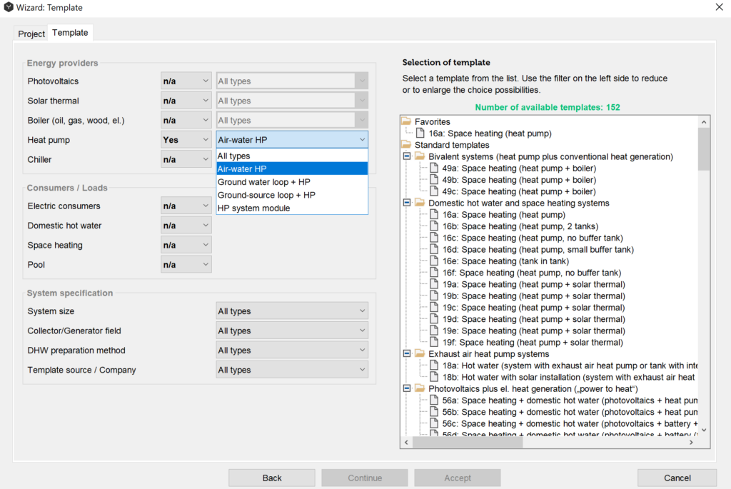
There are several types of the heat pumps, which can be chosen from the drop-down menu, such as:
Air-water heat pump extracts heat energy from the outside air.
Ground-water loop + HP extracts heat energy from a ground-water source.
Ground-source loop + HP extracts geothermal energy from the ground.
HP system module – systems designed according to the requirements and philosophy of FWS (www.fws.ch). FWS is a Trade Association for heat pumps in Switzerland, which unites the organizations and groups working for the promotion and dissemination of heat pumps.
Consumers, system specification and the proper template can be chosen according to the instructions and recommendations in the chapter Wizard about the Wizard.
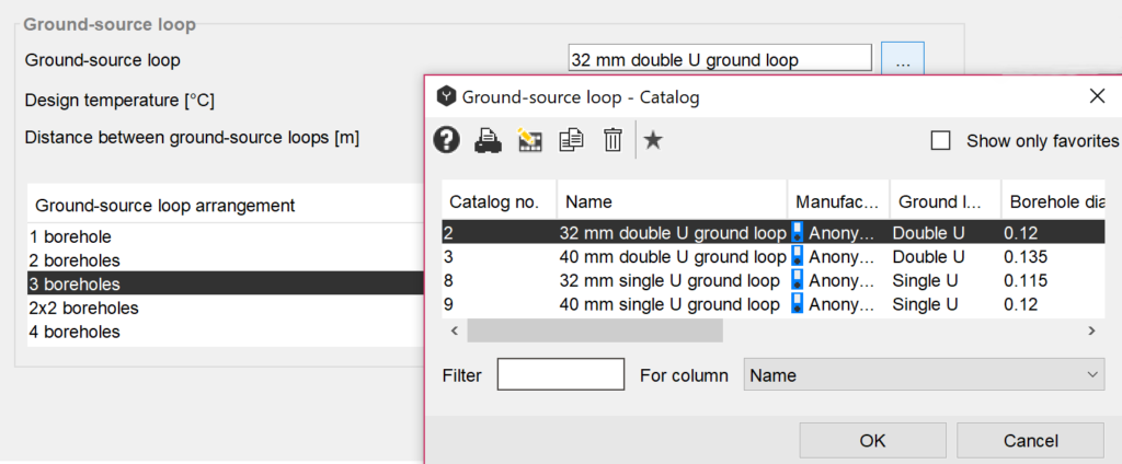
In the geothermal tab ground-source and ground-water loop parameters can be specified.
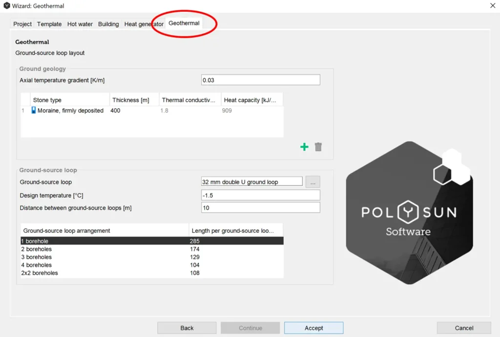
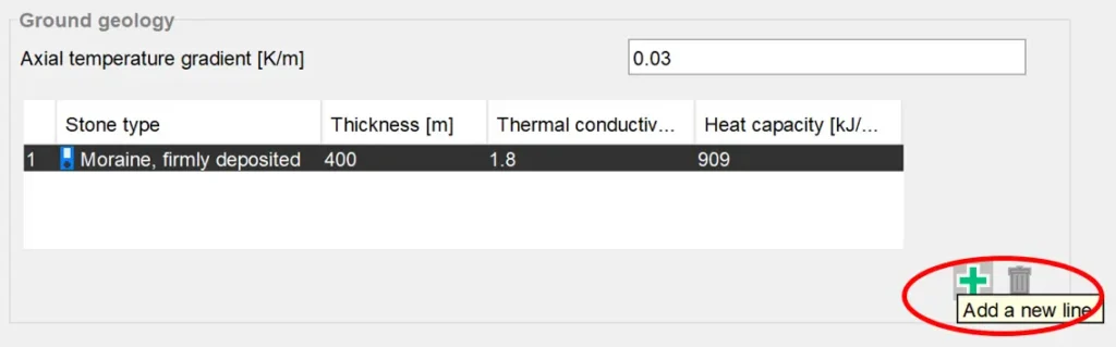
An important parameter for ground-source loops is the axial temperature gradient in the undistributed soil. In the ground geology part the earth layers can be added and then chosen from the catalogue corresponding to the given location. The layers can be added and deleted using the buttons at the right bottom part of the dialog window.
In the ground-source loop window, the loop can be chosen from the catalogue, design temperature and the distance between ground-source loops can be specified manually, the desired ground-source loop arrangement can be chosen from the table at the bottom of the window.
The design temperature is the average minimum temperature of the brine over 50 years.
Over a time the heat extraction from the ground cools down the reservoirs, because it takes time to replace this energy naturally. In order to replace extracted energy, a solar thermal system can be added to the heat pump. Then the ground-source loop will use the surplus of heat produced by the solar system in summer and store it in the ground for further utilization by the heat pump and increase its COP. In such a way, the solar system and the heat pump will complement each other and improve the overall efficiency. In order to evaluate the effect of the hybrid solar-geothermal system, preliminary simulation for a longer period (i.e. 10 years) can be run. If the ground has certain geological formation, such as rock or water-saturated soil, it can be used as a seasonal storage for solar thermal energy.
Photovoltaic systems can be also a perfect match to the heat pump, since they generate renewable electricity, which can be used by a heat pump.
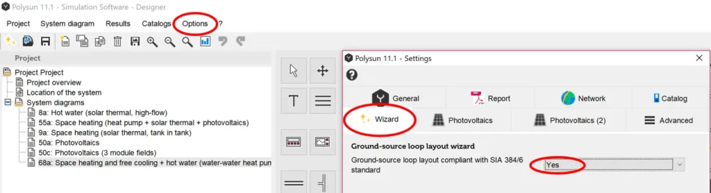
For ground-source heat pumps the local geology has to be evaluated. There are different standards and regulations which are specific for different locations. In Polysun, the ground-source loop layout can be chosen in compliance with the SIA 384/6 standard in ‘Options’ → ‘Settings’ under the tap ‘Wizard’. SIA 384/6 is an important valid regulation for the dimensioning of ground-source loops in Switzerland where it is obligatory to design geothermal systems according to this standard.
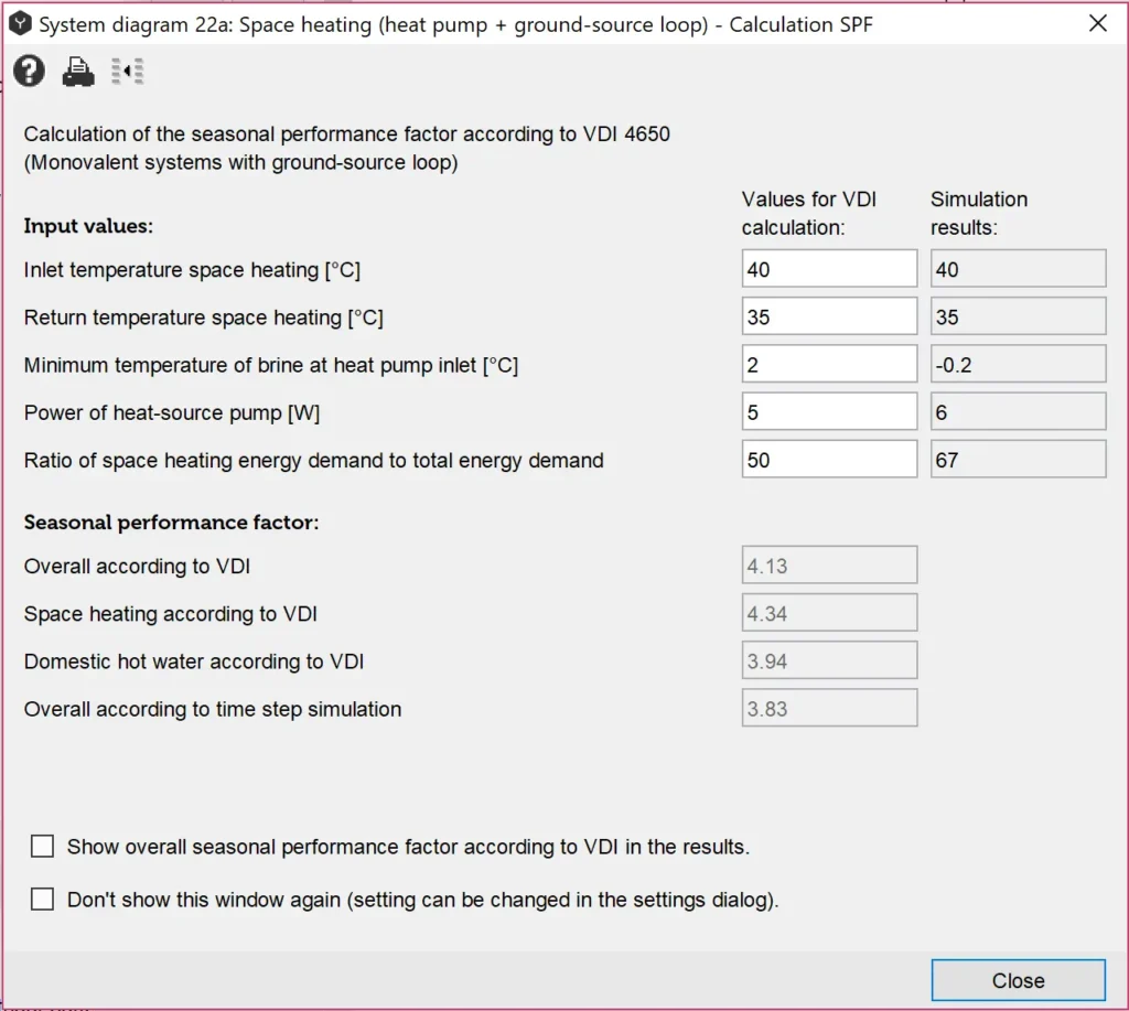
In Germany the guidelines VDI 4650 must be used. This standard can be activated in the ‘Options’ → ‘Settings’ under the tab ‘Report’.
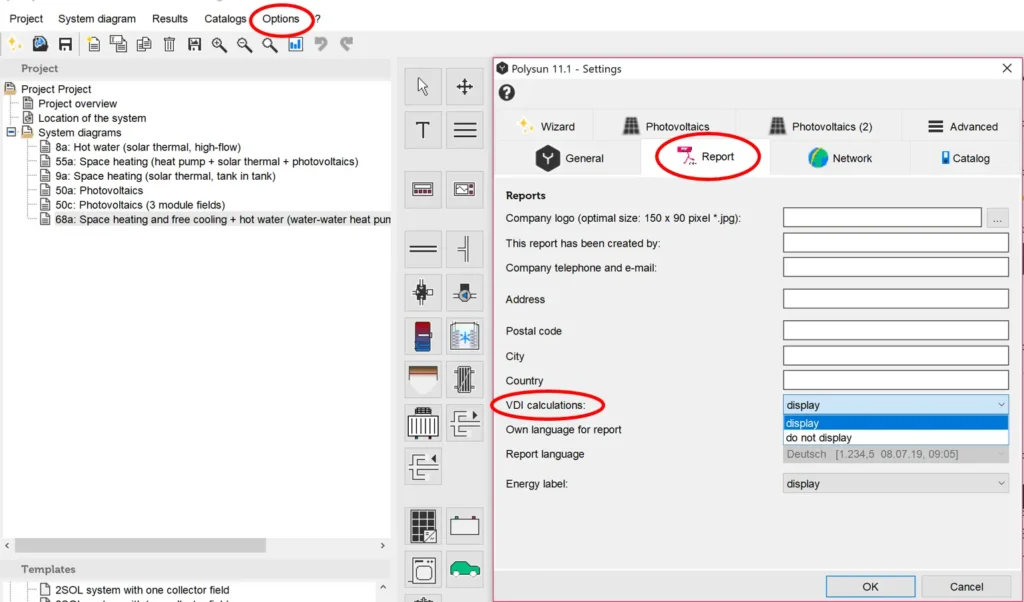
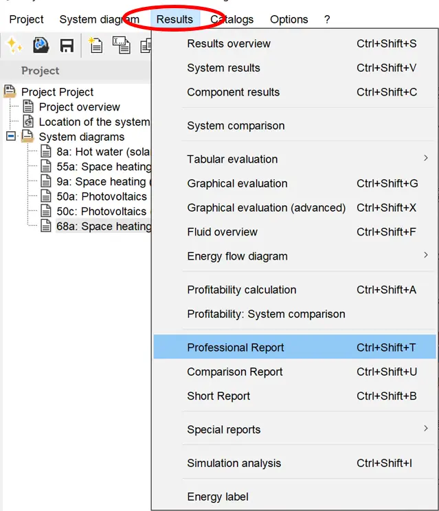
Then after choosing ‘Results’ → ‘Professional Report’, additional values will be required for calculations according to the VDI 4650 (Monovalent systems with ground-source loop).
The ground-source loop model in Polysun is a transient EWS model, which allows the detailed simulation of the hourly operation of the borehole heat exchanger and ground simulations. It allows predicting the operation of the designed ground-source loop. Therefore, an EWS file can be also imported and used for simulation in Polysun. It can be uploaded in the ground-source loop component dialog window.
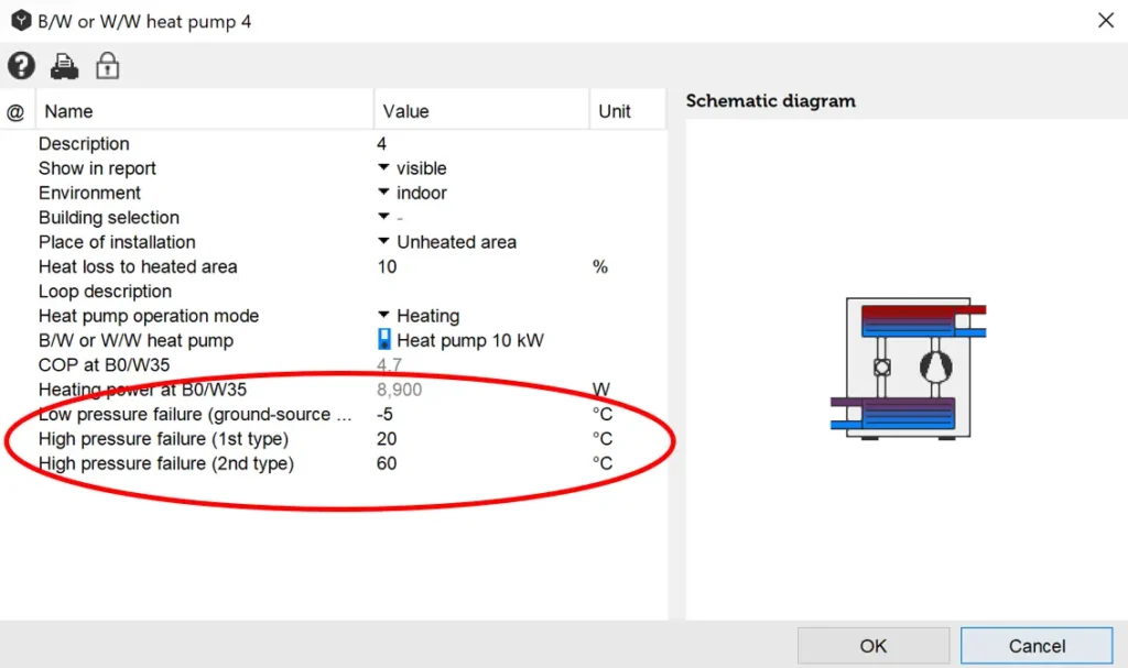
Heat Pump Low-Pressure/High-Pressure Failure
Air-water heat pumps have two self-protection temperature limits, brine/water-water heat pumps have three. If the temperature drops below the low-pressure failure temperature (brine/water-water heat pumps only) or exceeds the high-pressure failure temperature (2nd type), the heat pump cuts off. As a rule, the connected pumps are regulated by the heat generator controller, for which reason they keep running in case of failure. If the failure occurs too frequently (see component results), this could be due to the fact that hot water demand may no longer be met.
Possible causes for the failure:
- Low-pressure failure: the heat source or the borehole are too small
- The heat pump is too large
- Flow rate on source or consumer side is too large
- The temperature in the tank is too high or the position of ports does not fit controller settings
- The configuration of safety temperatures in the heat pump settings (double click on the heat pump) is incorrect