Irradiance Controller
The irradiance controller is a one-channel controller that regulates up to two components based on irradiance values. The controller is mainly used as a solar loop controller.
The controller has 1 (plus 1 optional) analogic inputs.
The controller has 1 (plus 1 optional) digital outputs.
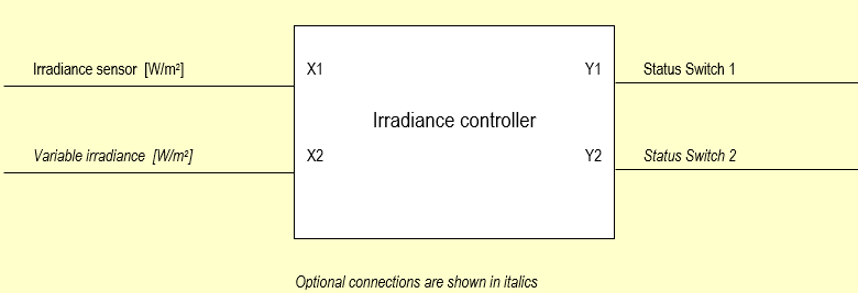
Block Diagram
The block diagram shows the employed measuring and controlling values
Controller Input Mask “Fixed Value”
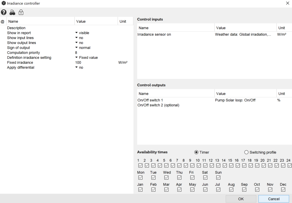
With this setting the pump cuts in as soon as the global irradiance is greater 100 W/m2.
Controller Input Mask “Variable Value”
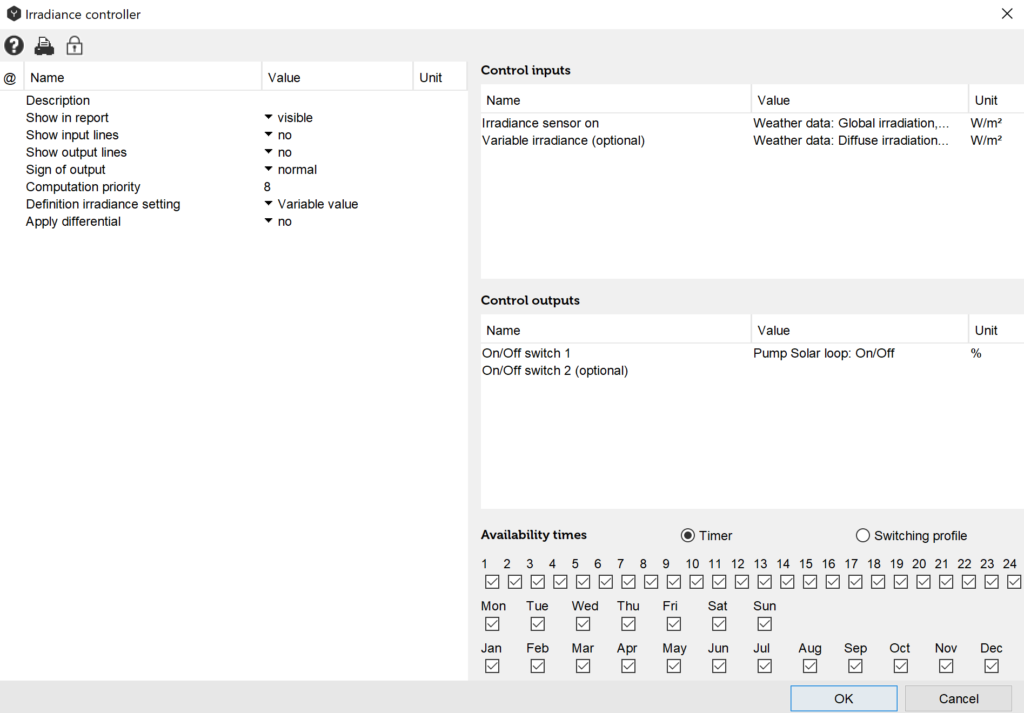
With this setting the pump cuts is as soon as the global irradiance is greater than the diffuse irradiance.
Input Values
Irradiance Sensor [W/m2]
The value refers to which irradiance should be measured. A distinction can be made between “Global irradiance”, “Diffuse irradiance” and “Long wavelength irradiance”. Enter a component from the list.
Variable Irradiance [W/m2] (Optional)
The value refers to the diffuse irradiance setting to be measured. A distinction can be made between “Global irradiance”, “Diffuse irradiance“ and “Long wavelength irradiance”. Enter a component from the list.
Description of Parameters
Description
The “description” value enables the user to assign controllers any name of number. Polysun assigns a consecutive number as a standard feature as different controllers are added chronologically in the hydraulic system
Sign of Output
The term “Normal“ means that digital output signals are controlled as intended in the switching logics. (Example: if X1>Fixed value or if X1>X2 the output of pump 1 is positive). The term “Inverted” means that the digital output signals are multiplied by -1. (Example: if X1>X2 the output Switch 1 is equal to zero).
Definition of Irradiance Setting
- Fixed value
If the irradiance measured by the irradiance sensor exceeds the specified fixed value the controller output switches to “on“. - Variable value
If the irradiance measured by the irradiance sensor exceeds the specified variable value the controller output switches to “on“.
Use of Hysteresis
If the hysteresis is used the following applies
- Cut-in hysteresis [W/m2]
If the irradiance measured by the irradiance sensor exceeds the reference value by the specified hysteresis the controller output switches to ”on “. - Cut-off hysteresis [W/m2]
If the irradiance measured by the irradiance sensor drops below the reference value by the specified hysteresis the controller output switches to ”off“.
Output Values
Status Switch 1
This digital output refers to the component to be controlled within the system. Select the relevant component from the list. For the switching valve the ”On“ status means that the output located on the switching valve and marked with “X“ is ”open”.
Status Switch 2 (Optional)
This digital output works just like output Status Switch 1. Select if required the component to be controlled from the list.
Overview of Control-Dependencies
Table: Control-dependencies of the irradiance controller
| Outputs | Parameter | Tip | Inputs | Function |
| Y1: Status Switch 1 Y1 = Y2 Y2: Status Switch 2 | Fixed value | If hysteresis is applied cut-in and cut-off criteria vary | X1: Irradiance sensor | Y1=0 if X1 < Fixed value [W/m2] Y1=1 if X1 > Fixed value [W/m2] |
| Y1=1 if X1 > Fixed value + Cut-in hysteresis[K] Y1=0 if X1 Fixed value + Cut-off hysteresis [K] | ||||
| Y1: Status Switch 1 Y1 = Y2 Y2: Status Switch 2 | Variable value | If hysteresis is applied cut-in and cut-off criteria vary | X1: Irradiance sensor X2: Variable irradiance | Y1=0 if X1 < X2 [W/m2] Y1=1 if X1 > X2 [W/m2] |
| Y1=1 if X1 > X2 + Cut-in hysteresis [K] Y1=0 if X1 < X2 + Cut-off hysteresis[K] |