Inverters
Automatic Inverter Layout
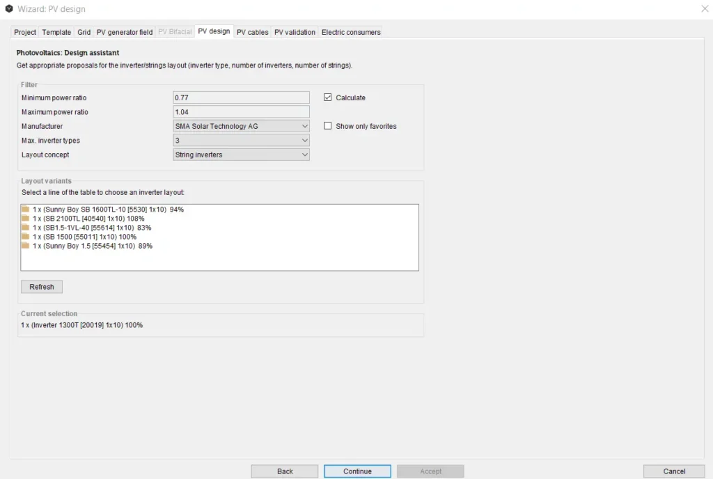
Polysun provides users with a useful inverter configuration tool, the “Inverter assistant“. The “Inverter assistant” can be started both via the provided assistants (photovoltaics page) and by means of the photovoltaic or PVT components (double-click on the relevant component and subsequent single click on the assistant symbol)
The inverter assistant provides the user with a list of possible configurations (hereafter called “Configuration system diagrams”).
Starting Situation:
The following data are given in the calculation of configuration system diagrams:
- Location
- Type of module
- Number of modules
Additionally the following values will also be considered in the calculation of the max. DC power (and partially also for the calculation of the min. and max. module temperature and therefore the max. MPP voltage and the max. DC current): orientation, , tilt angle, level of soiling, degradation, wind percentage and rear ventilation.
Configuration Result – Configuration System Diagrams:
Configuration system diagrams are characterised through the following data:
- Type of inverter
- Number of inverters
- Number of MPP trackers employed
- Number of strings (per inverter or MPP tracker)
Number of MPP Trackers Employed:
In case multi-string inverters are used Polysun attempts to reach the full or partial allocation of all MPP-controlled inputs. The configuration programme assumes here that strings were allocated uniformly.
Additionally the following data will also be displayed in the inverter assistant:
inverter manufacturer, number of modules per string and power ratio.
Power Ratio:
The term “power ratio“ refers in Polysun to the ratio between generator output at standard test conditions (STC) and the inverter’s maximum DC output.
Electrical Limit Values:
Configuration system diagrams are essentially selected based on the relevant electrical limit values. Polysun basically only reproduces combinations that comply with the limit values specified below (occasionally subject to particular operation and weather conditions). Voltage and current peaks can be calculated by means of the temperature coefficients included in the catalog.
Table: Electrical limits for the selection of the layout variants
| Nr. | Component | Limit value | Mode | Weather conditions |
| 1 | Inverter | Max. DC output | Max. irradiance | |
| 2 | Inverter | Max. DC voltage | Idling | Min. air temperature |
| 3 | Inverter | Min. MPP voltage | MPP | Max. air temperature |
| 4 | Inverter | Max. MPP voltage | MPP | Min. module temperature |
| 5 | Inverter | Max. DC current | MPP | Max. module temperature |
| 6 | Module | Max. system voltage | Idling | Min. air temperature |
| 7 | Mains | Max. phase imbalance |
Module Temperature Calculation:
Polysun enables module temperature to be calculated by the user. The following data are considered in the calculation: air temperature, irradiance, module gamma, wind percentage and rear ventilation.
If PVT collectors are used a fixed minimum (10°C) and maximum temperature (80°C) are assumed for inverter configuration purposes.
Phase Imbalance:
The configuration system diagrams provided by the configuration assistant comply with the requirement for a maximum phase imbalance of 4.2 kVA.
Thin-Film Modules – Galvanic Separation:
Thin-film modules should only be operated with a transformer or galvanic separation. This applies to all inverter configurations.
Filters/Tolerances:
Configuration system diagrams are eventually filtered, i.e. only given tolerance values will be allowed.
Filters/Tolerances Inverter Assistant:
The following fixed-sized filters will be used in the inverter assistant:
0.75 <= power ratio <= 1.25.
Additionally a fixed tolerance of 10% is given fort he maximum input power. A tolerance of 0% applies to all remaining maximum values.
There isn’t any guarantee that the automatic inverter layout wizard will find every solution suggested by a manufacturer tool. According to the conditions very detailed intermediate results could occur which then require limitations due to limited resources (memory, simulation time etc.). In those cases the user should design the inverter manually (chapter 2.2.2).
Manual Inverter Layout
‘Automatic’ or ‘Manual’ inverter layout shall be chosen in the dialog window by clicking on the photovoltaic component in the system diagram.
It is a common practice to start the project with a Wizard design and then adapt the automatic design version to the required conditions. If the system shall be slightly changed, manual design is also preferable.
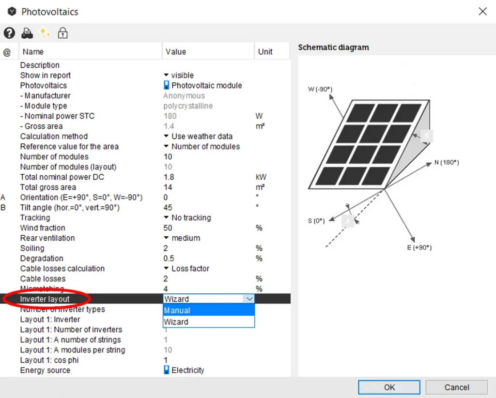
With a manual inverter design the following parameters can be changed:
Table: List of parameters for the manual inverter design
| Parameters | Description |
| Number of inverter types | Defines the number of inverter layouts (sub-layouts) in the combined layout. Up to 3 sub-layouts are possible. Each inverter layout (sub-layout) is defined by the inverter type, the number of inverters, the number of strings and the number of modules per each tracker. |
| Layout: Inverter | Selection of the inverter from the catalog. |
| Layout: Number of Inverters | Number of parallel connected inverters. |
| Layout: Number of strings | Number of strings in parallel per inverter. The maximum current of the PV generator should not exceed the maximum input current of the inverter, otherwise premature aging of the inverter will take place. |
| Layout: Number of the modules per string | Number of modules in series. |
| Layout: Orientation | The azimuth angle (0° = South, +90° = East, -90° = West, +/-180° = North) allows to define a different value per each tracker input. Optimal orientation depends on the local weather and climate conditions, however generally taken if possible in the direct south direction. |
| Layout: Tilt angle | Fixed angle at which PV modules are mounted from the horizontal plane, allows to define a different value per each tracker input. Tilt angle shall be chosen in order to maximize the exposure of the PV panel to the direct sunlight. |
| cos φ | Sets the cos φ (ratio between real power and apparent power called power factor) to a constant value. The default value is cos φ = 1 which means no reactive power. The usable power is only a real power. The grid operator may demand to set up certain power factor cos φ in order to avoid high additional load, which cannot be used to supply electrical devices. |
| Energy source | Energy source used as reference to calculate the economical and ecological results |
| Grid Wiring | Defines how single phase inverters are connected to the grid if there is more than one option. Refers to split-phase and high leg delta grids only. Options for split-phase grid: 1. ‘Split’ or line to neutral (120V) 2. ‘Default’ or line-to-line (240V) Options for high-leg delta grid: 1. ‘Split’ or line to neutral (120V) 2. ‘High-leg’ high leg to neutral (208 V) 3. ‘Default’ or line-to-line (240V) The default value is ‘default’. |
If the layout is changed manually in the photovoltaic component dialog window, it shall be checked afterwards through the Wizard for validity.
Manual inverter design is often used for inverters with multiple MPP trackers (multistring concept). Multistring inverters are simulated as one device with multiple, independent DC inputs and one AC output. Polysun supports up to 10 MPP-inputs. It is possible to manually define different sub-layouts for each MPPT-input available for the specific inverter type. The automatic layout algorithm always uses all the available tracker inputs. In the manual layout mode, you can set individual orientations and tilt angles for each tracker input by overriding the settings of the component. The PV-array pro MPPT input shall be homogeneous. Currently the multistring inverters can be simulated with only one module type.