Hot Water Tanks
Tank Types
With the aim of having an efficient system, in addition to the collector the thermal tank is of great importance. The choice of tank is decisive, from the moment that energy from the sun is not available and that occasional meteorological conditions occur for which the collector, for one or two days does not supply thermal energy. Three categories may be identified:
- Domestic hot water tanks (dimensions: twice the daily demand = 80-100 l per person)
- Tanks for hot water and space heating (dimensions: 100 l per MWh of heating demand)
- Seasonal tanks as tanks for several months (water storage tank, terrestrial seasonal thermal accumulator, etc.)
An average single family house with four people calls for tank dimensions of 300-500 l (domestic hot water only), 800-1500 l (with space heating) and over 30,000 l (seasonal tank). Combined forms also exist, in which the domestic hot water tank is integrated in a larger tank (the so-called combined tank).
Physical Aspects in the Optimization of the Hot Water Tank
The quantity of energy Q [J] necessary for a heat transfer fluid of the mass m [kg] with a heat capacity cp [J/kg/K] to heat a temperature ΔT [K] is calculated as: \(Q = m \cdot c_{p} \cdot \Delta T\)
Nevertheless the distribution of heat in the tank is to be taken into consideration: normally the water is stratified at different temperatures. At the top, where the hot water is withdrawn, the layer with the hottest water is found (less dense water) and at the bottom there is the coldest layer (denser water). This stratification is desirable and for this reason the generation of the least possible turbulence is sought during the transfer of heat to the tank and the withdrawal of water.
Defining the dimensions of a tank is an exercise in proportion, in which various contrasting aspects are weighed out:
- A large tank has a great capacity
- A large tank needs a lot of energy to be “charged up”
- The higher the temperature, the greater the quantity of stored energy.
- The higher the temperature, the greater the tank losses
Usually it is sought to keep ready the quantity of water for daily consumption at the right temperature (or a few degrees higher) and to keep the rest of the tank temperature lower. This way the (cover of) hot water is always guaranteed and the losses from the tank are minimal. In the summer season though the tank can become overcharged, but having sufficient quantities of solar energy at this time allows acceptance of higher tank losses. The interesting fact is that the demand can be covered even in periods of bad weather. Since the water tank can be heated up to 95°C (also to 100°C) and the water reaches the desired temperature only when it is withdrawn and mixed with cold water, one can continue for several days.
Sizing the Combined Tank
The combined tank is used when one wants to produce domestic hot water and space heating from a single solar energy system. Since the heating circuit and that of drinking water should not be united for hygienic reasons, the domestic hot water boiler tank is integrated into the main tank with the combined hot water tank. This has three main advantages:
- The surface area of the tank can be kept small (only the surfaces of the main tank), in this way heat losses are minimal.
- The domestic hot water tank, which normally requires higher temperatures than the space heating tank, can be placed in the warmer upper part of the main tank.
- A higher consumption of hot water doesn’t cause turbulence in the main tank. This way the stratification is better maintained.
The principal of a combined tank resembles that of a continuous flow heater. The domestic hot water, in a system of separate pipes, passes through the main tank where it is heated. Because this heat exchange needs to be as efficient as possible, the interior tank should have thin walls and be made of a material with high thermal conductivity.
The internal tank is located preferably in the upper half of the main tank (5-10 cm below the top cover). Its size should correspond to approximately double that of daily consumption.
The heat losses at the connections (see following paragraph) can be indicated in the second part of the dialogue window. The values proposed by Polysun are equivalent to well insulated s-bending connections.
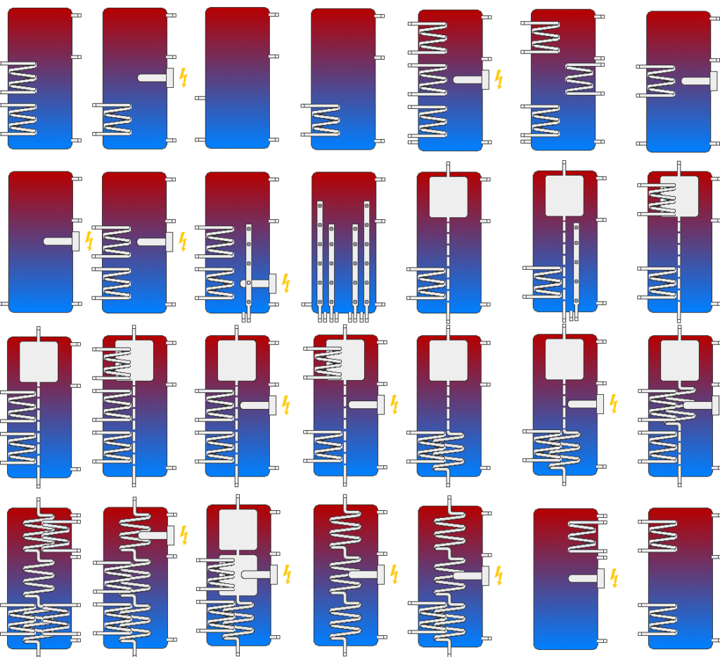
With the Polysun Designer one can create a new tank with a great variety of possibilities.
With the selection of a new tank a new catalog entry is created. In creating a new tank the standard components for the internal elements are established (coil heat exchanger, stratifier lances, auxiliary heating, etc.) The choice of internal elements are set in the tank catalog, where it is possible to eventually create new specifications in the catalog for the internal elements.
The following figure shows some exemplary possibilites:
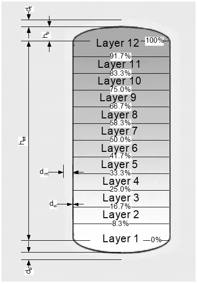
Tank Model and Relative Dimensions
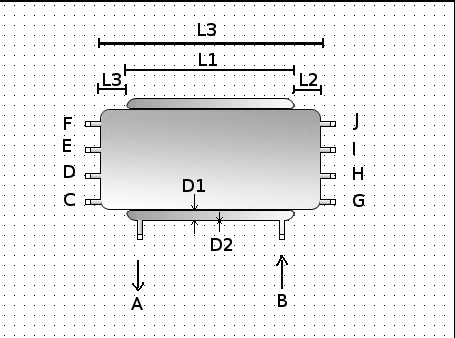
For measurement, the height of the cylindrical part of the storage tank, the bulge height and the volume are important. By means of these three values the diameter is obtained. With the height of the tank we don’t mean the total height, including the thermal insulation, but only that of the cylinder.
The interior of the tank is subdivided into twelve isothermal layers. The fluid contained by the bulge is always added to the lower and higher layer, for which the relative volumes are greater in respect to those layers from two to eleven. For the difference in density, the hot layers spread towards the top, the cold ones towards the bottom. In the border area there is heat transmission by means of conduction. A convective mix is ignored.
The internal components of the tank shown are not correctly positioned from a graphic point of view. The determinant indications regarding the positioning are those in percentage in the tank catalog.
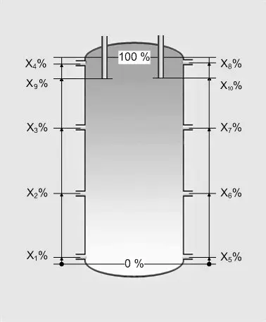
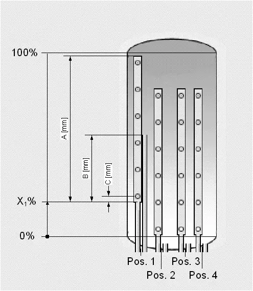
A tank has a maximum of ten connecting pieces available. The positioning in percentage is always measured from the lower part of the cylinder. (Note: not from the bottom of the tank). Likewise the connecting pieces are numbered from the bottom left towards the top and again from the bottom right towards the top.
The simulation does not allow unconnected open flanges. The incoming fluids have to be able to leave the tank by means of other connecting pieces.
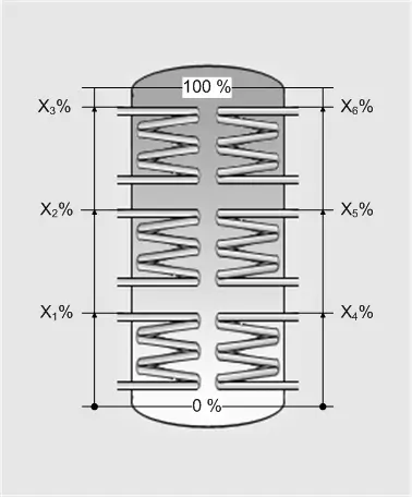
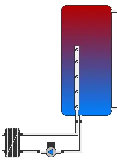
A tank has up to six coil heat exchangers available. Three coil heat exchangers can be connected to the left internal tank wall and three to the right wall of the tank. This system diagram is illustrated in figure 20. The height of the coil heat exchangers is indicated in millimeters in the catalog “Coil heat exchangers”, its position in the tank is indicated in percentage from the top edge of the coil to the lower part of the cylinder.
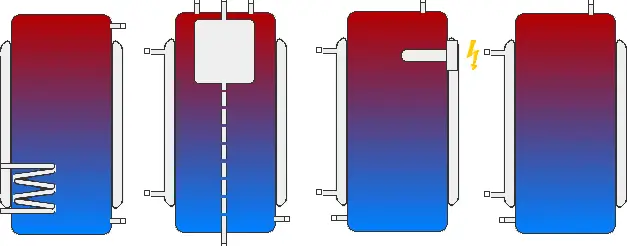
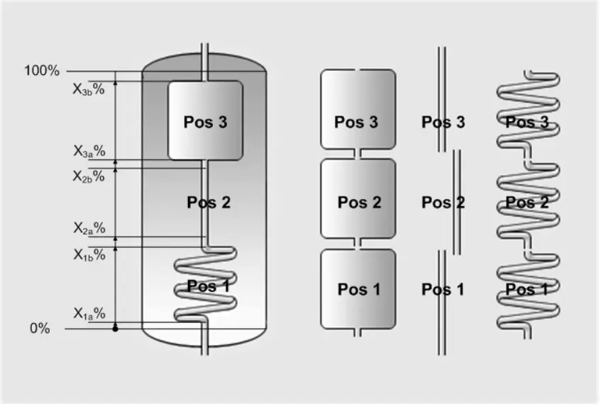
The three internal elements “tank”, “tube” and “coil heat exchanger” are defined as shown in the following figure. Furthermore they have available positions from one to three, that can be substituted by choice with the three objects.
The volume of an internal tank is defined in function of the relative surface and the relative positioning. The height of the internal tank is calculated on the basis of the indications of its position.
It is possible to have up to four stratifier lances, arranged and numbered from left to right. In the tank catalog only the position is defined, the measurement is indicated in the “stratifier lances” catalog.
Thermal Insulation and Losses at Connections
The design of seasonal tanks depends strictly on the possibility of thermal insulation and the way in which the heat lost from the tank can return to become useful for heating the space (for example when the tank is in the centre of the house). Relative to losses, a large tank is more convenient than a small one because the relationship between surface and volume (even in proportion) is lower when the tank is large.
Normally thermal insulation with a thickness of 15-30 cm is used (with a heat conductivity coefficient of λ = 0.04 W/m/K). The top cover can be thicker because hotter water is found there. The bottom cover, on the contrary, can be much thinner. In certain cases it is actually worth the trouble to omit the thermal insulation on the lower side. This way the environmental heat helps to warm the cold water.
In the course of planning, these various aspects need to be taken into consideration. Also the particular characteristics of heat input (from the collector and auxiliary heating) and from heat output (consumption of hot water and heating) are determining factors.
The illustration of the dialogue window for the definition of relevant parameters of the tank in Polysun follows:
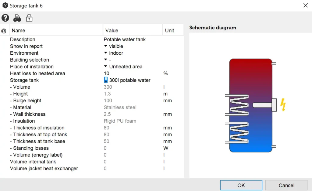
To modify the properties of the tank (for example the volume), you can open the tank catalog by double clicking on the  catalog symbol in tank. At this point it is possible to select another tank or to copy and adapt the one in use (at the Professional and the Designer level).
With “connection losses” we mean that the pipes from and to the tank can be the source of considerable losses. For example in the hot water connection pipe (in stasis) the hot water continually rises, it cools and descends again in the tank. This can cause considerable heat losses. Regarding this, two solutions exist:
S-bending the pipes and insulating the connections: right at the output of the tank a downward curving piece is installed. Here the water cools, but remains at this point in the pipe, impeding further exchange of hot water. If and how to curve and insulate well the connection can be chosen in the tank catalog. For the simulation, losses at the connections are determined, that are defined in the flanges (connections) catalog.
The extent of losses also depend on the temperature of the storage tank room. This can be indicated locally in the project. The indicated values are valid for S-bent and well insulated connections. Without these measures the losses at the connections are 10 times higher.
Charging the Tank
To transfer the heat from the collector to the tank in the most efficient manner, different methods are employed:
- Internal heat exchanger: the fluid is pumped through a coil that is found inside the tank. The pipe in the form of a spiral should have a wall that is quite thin with a large (external) surface (for example thermal fins) and made of material with a good thermal conductivity (for example copper). The heat is transmitted by means of a (free unilateral) convection to the fluid in the tank.
- Coat heat exchanger: The fluid flows around the tank through the coat heat exchanger encasing the tank. The heat is transferred to the fluid in the tank through (one-sided free) convection.
- External heat exchanger: the fluids of the collector and that of the tank are conducted one near the other in a counterflow plate heat exchanger and exchange heat by means of thin fins, which separate the two liquids. This is an efficient model of heat exchange in which, depending on the capacity of the exchanger and the ratio of temperature and flow, up to 99% of the thermal energy can be transmitted from one liquid to another. Normally on the tank side of the heat exchanger a circulation pump is also found. After the heat exchange, the fluid is released to the tank by means of one of the following system diagrams:
- Direct introduction: the heat transfer fluid is withdrawn and introduced directly into the tank.
- Introduction by means of a stratifier lance: inside the tank there is a vertical tube with about a dozen apertures covered externally by movable caps, similar to a flute. The fluid rises inside the tube until its density is greater in respect to that present in the corresponding point in the tank, and then flows out. The fluid is therefore “deposited” exactly at the point in which it has the same temperature as the tank’s liquid. This way an optimum stratification is guaranteed in the tank. Polysun doesn’t yet contain stratifier lances with internal heat exchangers, whose simulation is carried out by means of an external plate heat exchanger, as indicated in the following figure. A fixed flow rate must be selected in the pump, in order to have a balanced flow capacity (\(m_{1} \cdot {cp}_{1} = m_{2} \cdot {cp}_{2}\) ).
There are also cases in which two exchangers are employed, one at top and one at bottom of the tank. Depending on the solar irradiation and the temperature inside the tank, the energy is used for pre-heating (only the lower exchanger) or for the production of domestic hot water (both exchangers).
Withdrawal of Water from the Tank
There are two ways to withdraw heat from the tank:
- Direct withdrawal from the tank: the hot water is taken directly from the tank and is brought together with cold water to the desired temperature by means of a mixing valve (if the temperature of the highest layer in the tank is too high).
- Internal heat exchanger: the heat is withdrawn from the tank by means of a coil heat exchanger. The hot water is brought together with cold water to the desired temperature by means of a mixing valve.
- External heat exchanger: The heat is withdrawn from the tank by means of a plate heat exchanger. The control of the flow indexes must be regulated in such a way that the produced hot water has the desired temperature.
Deciding whether to choose a heat exchanger or direct drain depends on the conception of the circuits. There are systems in which the collector loop and the tank are operated with water, in some only the collector loop is operated with a mix of water-glycol and in others the collector loop and the tank are operated with a mix of water-glycol. To make this kind of choice it is useful to take the following into consideration: