Mixing Valve Controller
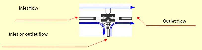
The mixing valve controller is a one-channel controller that regulates the mixing ratio of two different inflows so that the desired outflow temperature can be reached. Such outflow temperature may be specified through a constant or variable value. This analogic output enables to control a three-way valve and put in place this way a scalding protection.
The controller has 2 (plus 1 optional) analogic inputs.
The controller has 1 analogic output.
Remark: as during a simulation time step the mixing ratio remains constant its calculation should be based on temperatures that are as constant as possible. You can therefore beneficially use to this end the large volumes preceding the mixer and not the immediately adjacent pipes (for example temperature in tank layers or connections).
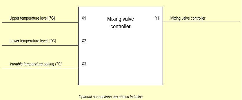
Block Diagram
The block diagram shows the employed measuring and controlling values
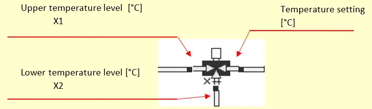
Definition of Mixing Valve
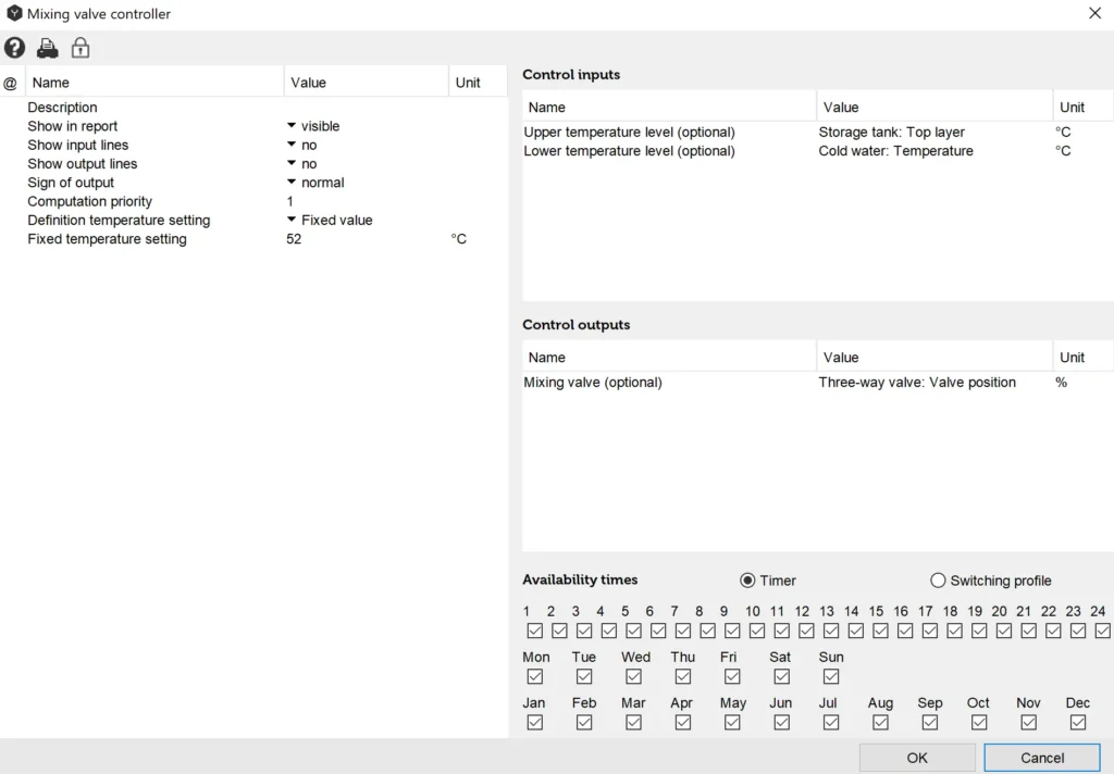
Controller Input Mask “Fixed Value“
Controller Input Mask “Variable Value“
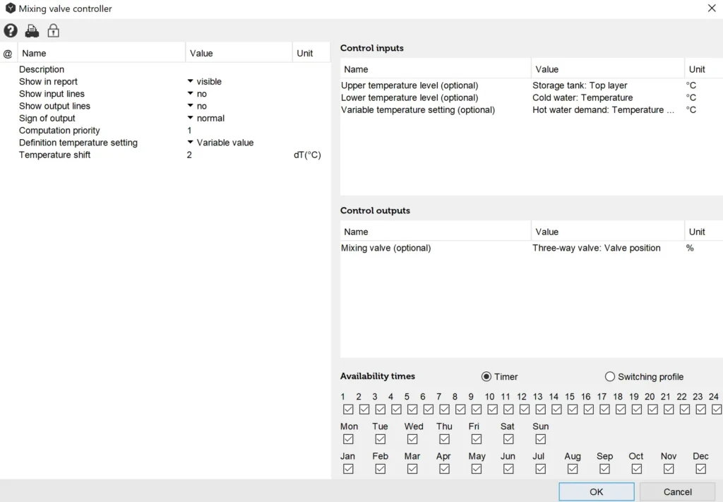
With this setting the mixing will be performed based on the variable temperature setting “Hot water demand: temperature setting“ plus 2°K according to the selection of the temperature shift. The hot water temperature setting will be defined in the user profile of the project overview. The temperature shift will enable to compensate the temperature drop between mixing valve outflow and hot water tap.
Input Values
Upper Temperature Level [°C]
The value refers to the component in which the upper temperature level is measured. Select the relevant inlet pipe to the mixing valve or the previous tank connection.
Lower Temperature Level [°C]
The value refers to the component in which the lower temperature level is measured. Select the relevant pipe to the mixing valve on “Input X” (see figure “Definition of mixing valve“)
Variable Temperature Setting [°C] (Optional)
The value refers to the temperature setting to be achieved.
Description of Control Parameters
Description
The “description” value enables the user to assign controllers any name of number. Polysun assigns a consecutive number as a standard feature as different controllers are added chronologically in the hydraulic system
Sign of Output
The term “Normal“ means that digital output signals are controlled as intended in the switching logics.
“Inverted” should not be used.
Definition of Temperature Setting
- Fixed value
The mixing valve will be regulated by means of the measured inlet temperatures so that the specified “Fixed value” temperature may be reached at the outflow of the mixing valve. - Variable temperature setting
The mixing valve will be regulated by means of the measured inlet temperatures so that the specified “Variable value“ temperature may be reached at the outflow of the mixing valve allowing for the temperature shift.
Definition of Temperature Shift
- E.g. 5 [K]
The temperature shift value enables to compensate the temperature drop between the outflow of the mixing valve and the hot water tap. If the value is positive the outflow temperature will be increased by this value. If the value is negative the outflow temperature will be reduced by such value.
Output Values
Mixing Valve Position
The output “Mixing valve” allows to define the position of the valve. The output regulates the branching ratio of inputs so that the specified temperature setting may be reached.
Overview of Control-Dependencies
Table: Control-dependencies of the mixing valve
| Outputs | Parameter | Tip | Inputs | Function |
| Y1: Mixing valve status | Fixed value | Adjust mixing valve to – controlled value | X1: Upper temperature level [°C] | Y1=f(X1,X2) for the specified temperature setting |
| X2: Lower temperature level [°C] | ||||
| Y1: Mixing valve status | Variable temperature setting | Adjust mixing valve to – controlled value | X1: Upper temperature level [°C] | Y1=f(X1,X2,X3) for the specified measured value of variable temperature setting plus temperature shift |
| X2: Lower temperature level [°C] | ||||
| X3: Variable temperature setting [°C] |
Valve Used as Switching Valve
The switching valve can be operated in the easiest possible manner through the temperature controller.
The mixing valve controller is not suitable for this use.
The switching valve should be connected so that the directions of flow match the figure.