Systems
Grid-Connected PV Systems
The project can be started from the menu Project – New project or by means of the Wizard.
In the Wizard first the location has to be defined either from the map or from the database. After the location has been defined, in the next step you can choose the criteria for the PV grid-connected system and the corresponding system template.
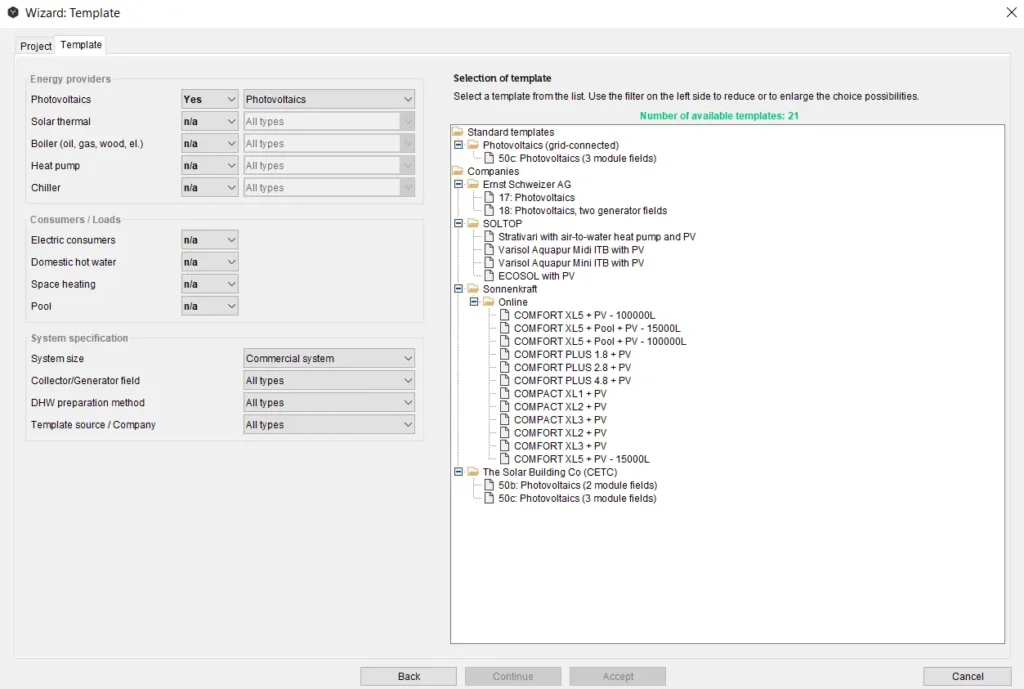
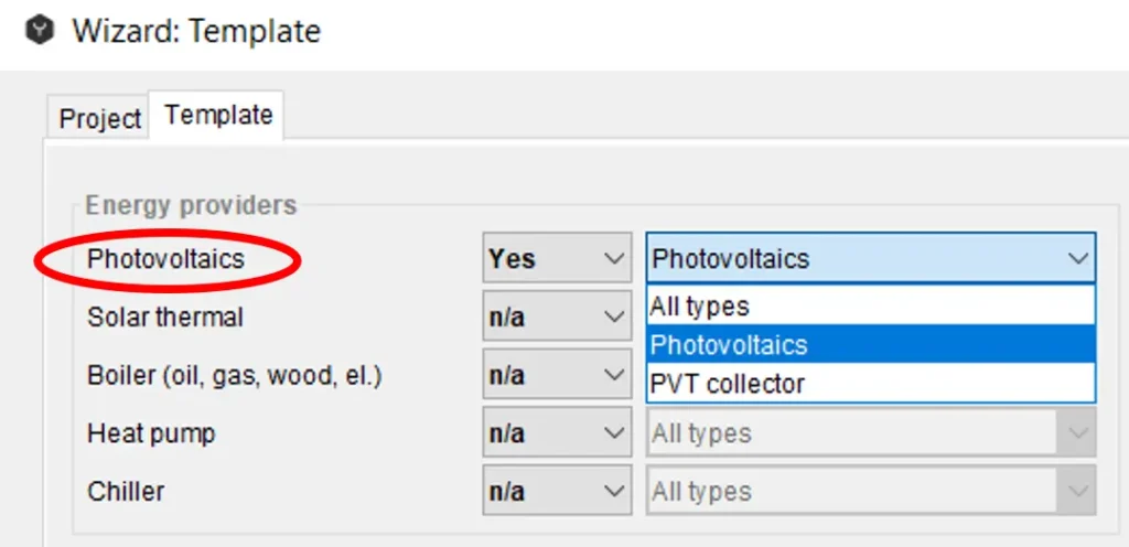
In the drop-down menus, you can first choose in the upper left side of the dialog window what kind of energy providers you would like to have in your project. Here you can choose one or more types of providers.
‘Yes’ means this energy provider must be in the system.
‘No’ means this energy provider must not be in the system.
‘N/a’ (not applicable) means that this type of energy provider is not a criterion for the selection of the system (the list will show systems with and without this component).
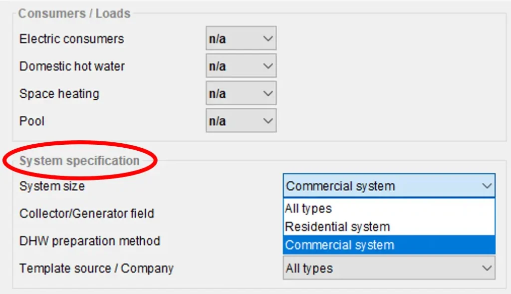
Next you will have to define the type of energy consumers/loads available for your project:
As a next step, the system specification can be defined as follows:
Table: Photovoltaic systems specification
| System specification | Types |
| System size | Residential system Commercial system |
| Collector/Generator field | Single field Several fields |
| Template source/company | All standard templates All company templates |
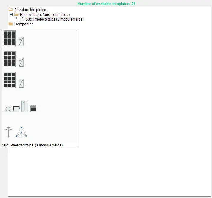
Then the templates will be shown on the right side of the dialog window filtered in accordance to the defined parameters. The pre-view of the template is available, when you hover the mouse cursor over the template name. You can choose the most appropriate template by double-clicking on it. If there aren’t any templates which meet all the requirements of your system, then you can choose the closest one and change it accordingly.
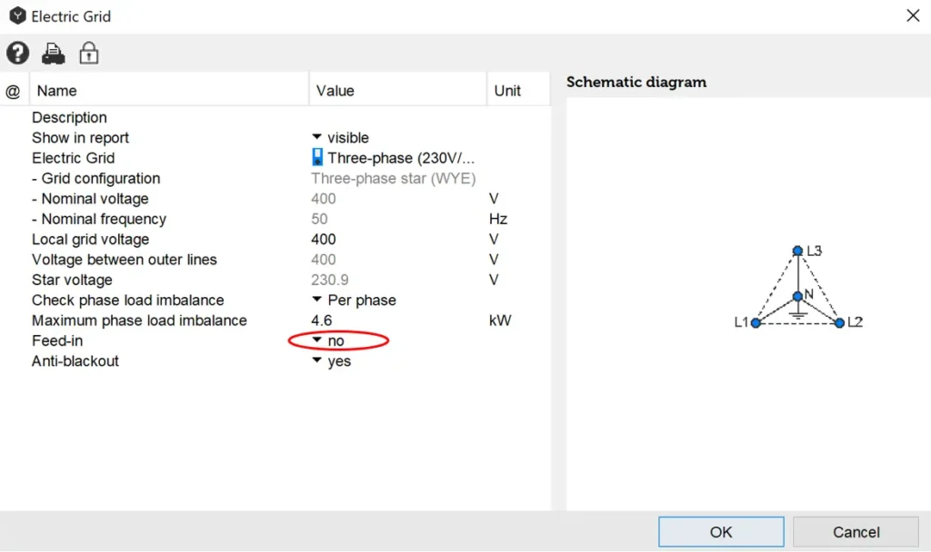
When the template is chosen, in the next step the appropriate grid configuration, nominal voltage and nominal frequency can be defined from the catalog.
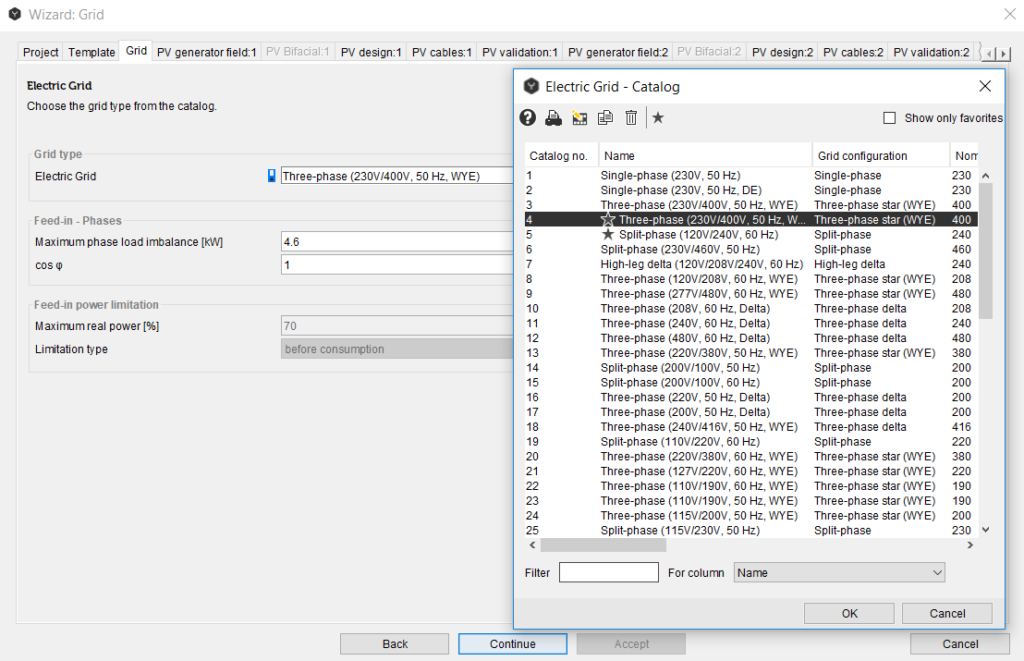
Then the ‘Maximum phase-load imbalance’ according to the local parameters as well as ‘cos φ’ shall be determined. The maximum phase-load imbalance is important for 1-phase and 2-phase inverters, when the load must be balanced.
‘Cos φ’ is the ratio between real power and apparent power (called also power factor) to a constant value. The default value is cos φ = 1 which means no reactive power. The usable power is an active power. A certain degree of reactive power cannot be avoided in AC grids. The grid operator may demand to set cos φ between 0.95 and 1 in order to avoid high additional load, which cannot be used to power electrical devices. Reactive power leads also to greater conduction losses.
‘Maximum real power’ is a limitation of active power related to the peak power. The photovoltaic power station may feed into the grid not more real power than the indicated peak power fraction. The purpose of the power limitation is to avoid feed in high midday peaks.
‘Limitation type’ can be “before consumption” and “after consumption”. “Before consumption” means limitation of the inverter power independently from self-consumption or battery charging. “After consumption” means limitation of the inverter power taking into account self-consumption or battery charging. In this case the charge controller has to be used for power limitation.
If the ‘Unlimited’ option is ticked, then it is not important for the system.
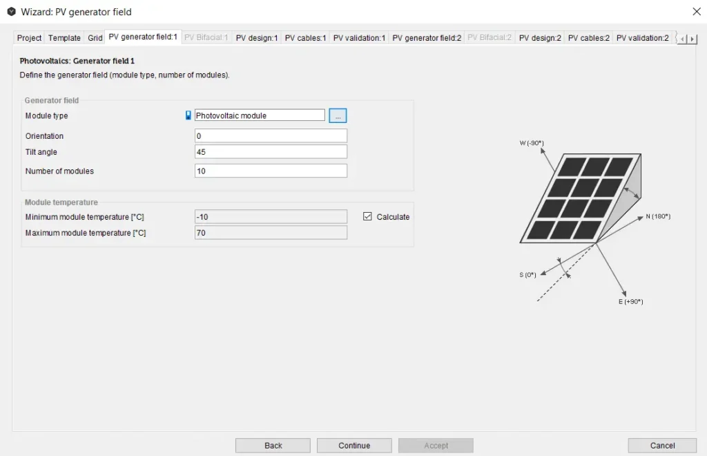
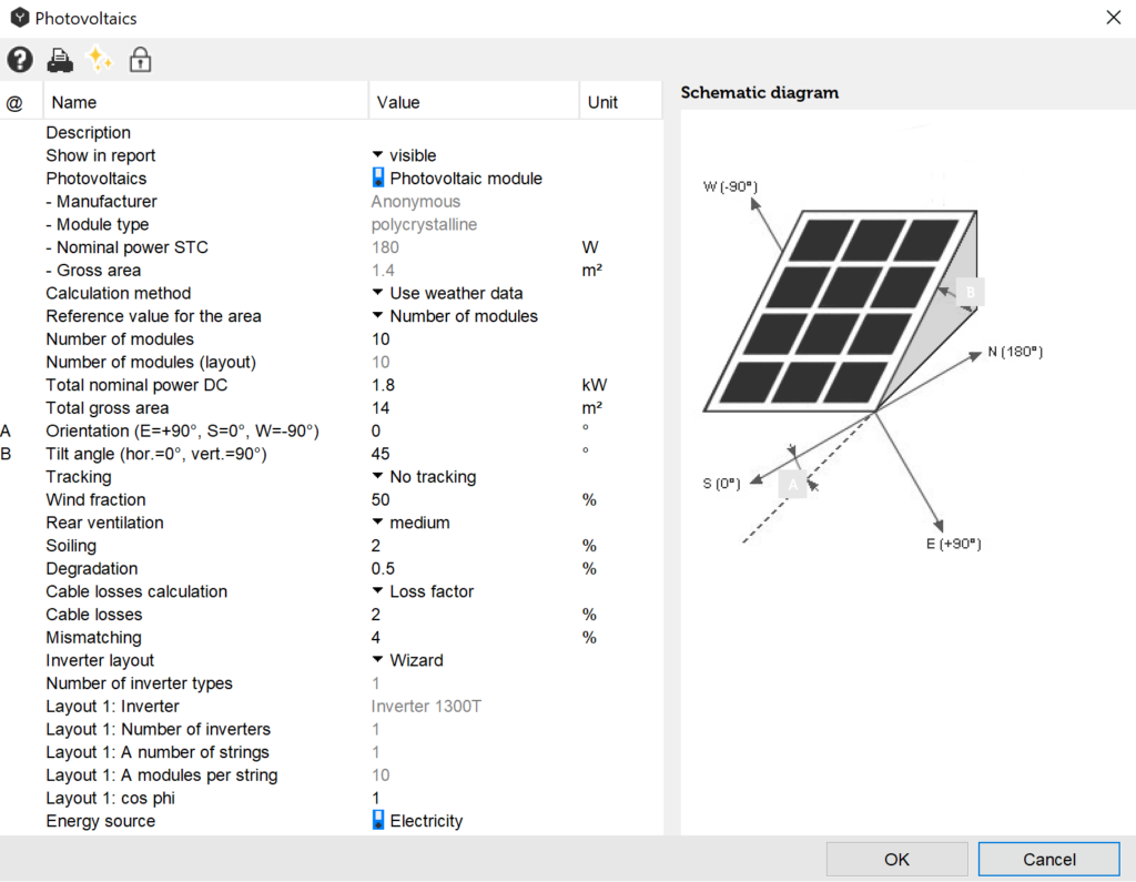
In the next step of the Wizard the PV Generator can be specified. You can find more detailed information about photovoltaic modules and their parameters in the section PV Modules and Parameters PV Modules of this User Guide.
The module type can be chosen from the catalog.
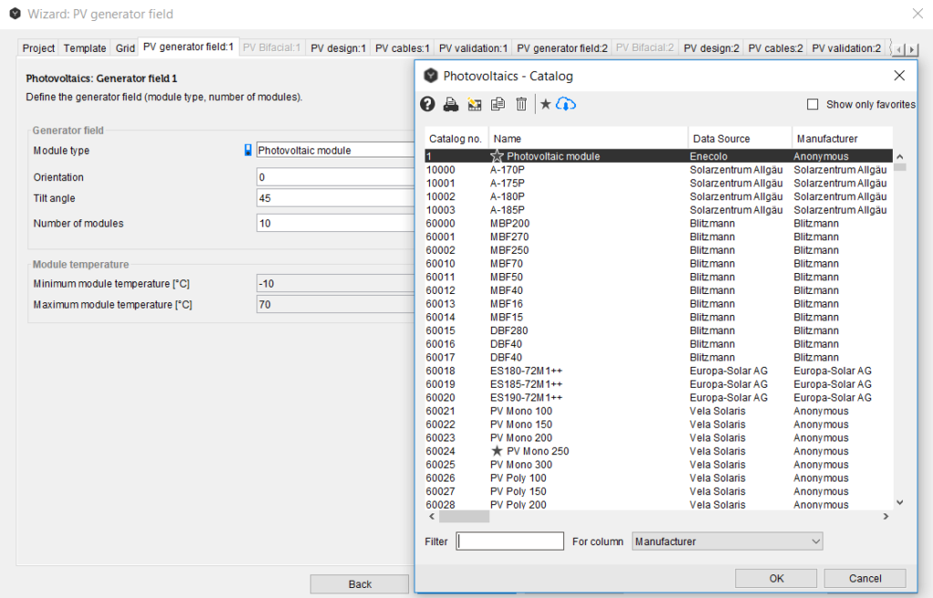
The important parameters for PV module disposition are as follows:
- Orientation: horizontal or vertical
- Tilt angle
- Roof width [m]
- Roof depth [m]
- Number of modules, which can be inserted manually or be calculated automatically for a complete roof occupation.
Maximum and minimum module temperature are important parameters for the inverter layout. They can be inserted manually or calculated automatically using the embedded Polysun algorithm.
The next step in the Wizard is the inverter layout. In this section Polysun gives a number of suggestions of the inverter/string layout based on the system requirements. Inverters are described in detail in chapter Inverters.
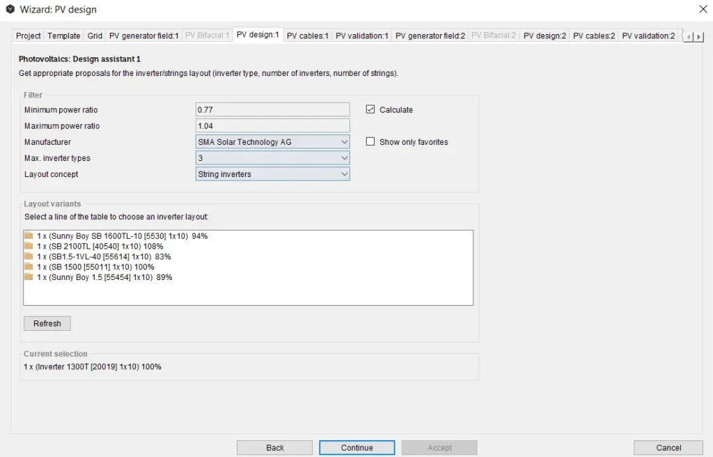
Table: Filtering the layout variants
| Filter | |
| minimum power ratio | The layout results are filtered according to the power ratio (min-max power ratio. The value will be ignored if no results are found within the range. In Polysun it is the ration between maximum DC power and total nominal power of the generation field (number of module per inverter times nominal power Pmpp of the module). A bigger ration means that the inverter is overdimensioned. The optimal value depends on the orientation, tilt angle, region and reactive power. |
| maximum power ratio | |
| manufacturer | Producer or distributor of the inverter can be chosen from the drop-down list. |
| Maximum inverter types | Polysun can calculate combined layouts with up to three different inverter types. |
| Layout concept | One of the following concepts can be chosen: Microinverters – 1 inverter pro module String inverters – 1 string per MPP-tracker Central inverters – at least 2 parallel strings per MPP-tracker Uniform – 1 type per layout variant Mixed – allow mixing different inverter types in one layout variant. The combination of different concepts is not allowed. |
After all the filters have been chosen, Polysun shows layout variants. The power ratio is indicated by the percentage, e.g. [100%]. A click on the arrows or double click on a line opens the tree with the layout details.
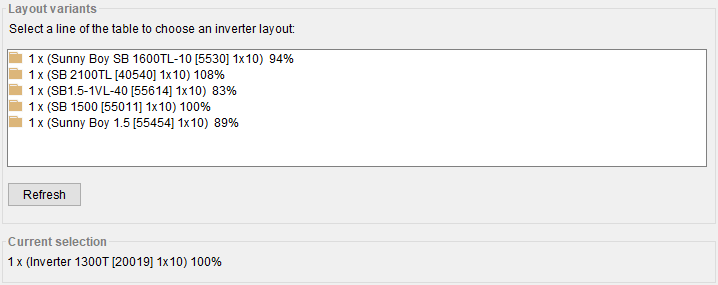
Sorting configuration of inverter layouts is used from the ‘Settings’ under the tab ‘Advanced 2’.
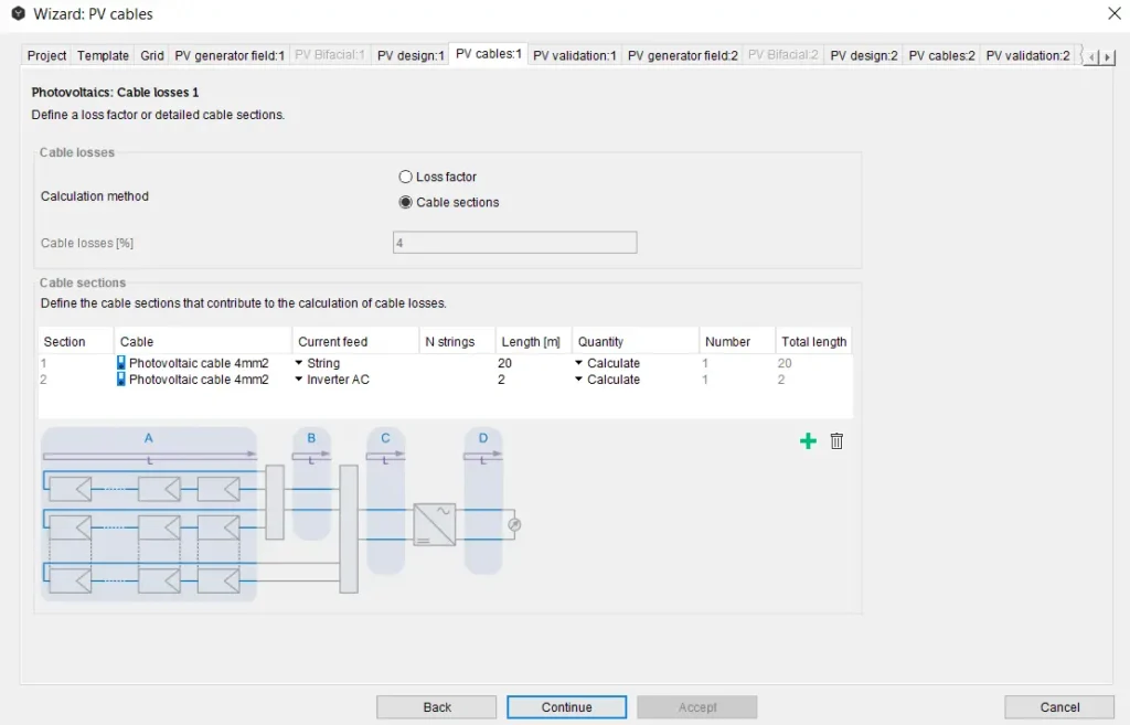
In the next step the cable losses are defined by the simple loss factor or detailed cable sections.
‘Loss factor’ defines DC cable losses at nominal power. The effective loss factor depends on the input power. Polysun calculates the loss factor in order to reach this value at nominal power. Total losses are much smaller than the loss factor, because the system rarely operates at a nominal power and therefore the loss factor is not constant.
In the ‘Detailed cable sections’ the cable sections which contribute to the calculation of the cable losses can be specified manually.
The cable section parameters, which shall be specified are:
- Cable type with an appropriate conductor diameter can be chosen from the catalog;
- Current feed defines how Polysun will compute the current through this cable section:
- String – DC current of a single module or string;
- N Strings – DC current of a specific number of strings (for example if this cable section is used for a part of the strings only);
- Inverter DC – total DC current of all strings together, at inverter input;
- Inverter AC – AC current at inverter output.
- N strings – number of strings for the current calculation. Only applicable if the current feed is set to N strings;
- Length (back and forth) for unit:
- per string (current feed “string);
- per inverter (current feed “N Strings”, “Inverter DC”)
- per inverter and phase (“Inverter AC”);
- Quantity defines how Polysun should compute the total length of the cable section:
- Calculate number of units automatically from number of strings and/or number of inverters;
- Number – enter a number of units manually.
- Number of units of the specified length
- Total length of the cable section, as it is inserted in the cable loss calculation.
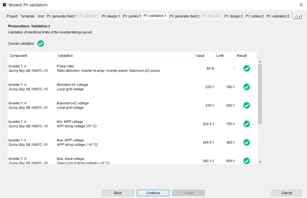
The next step in the Wizard is the validation of the electrical limits of the inverter/strings layout. Validation can show an OK (green tick), error (red cross) or warning (yellow triangle) for each component in the system.
In the next step of the Wizard first the number of electricity consumption profiles shall be chosen as well as the consumption profile types from the catalog.
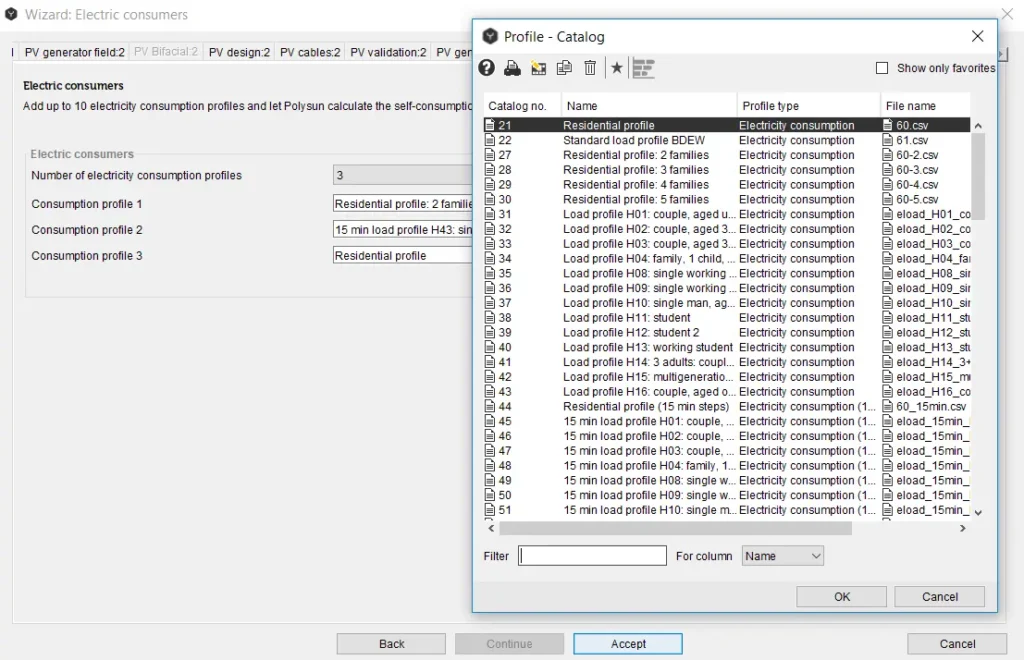
The annual consumption can be changed manually and the profile will be scaled up/down according to this number. After simulation Polysun shows the main system output parameters in the Results overview.
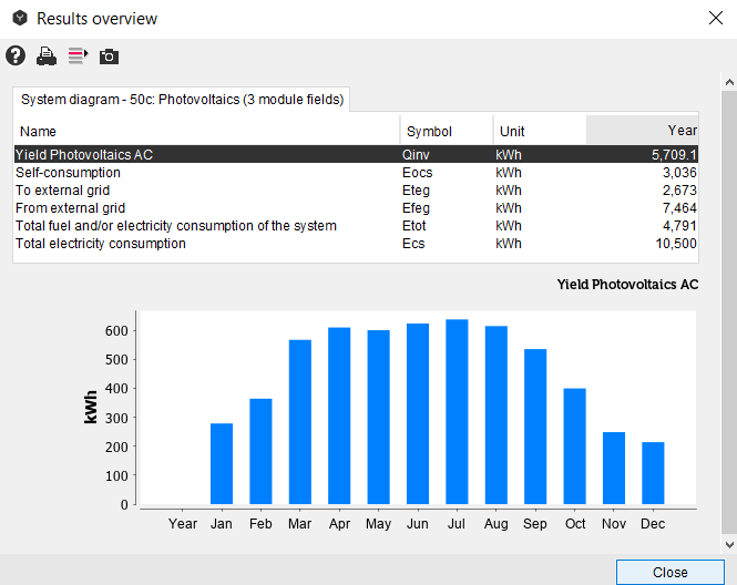
The more detailed results can be found in the Results → Component results.
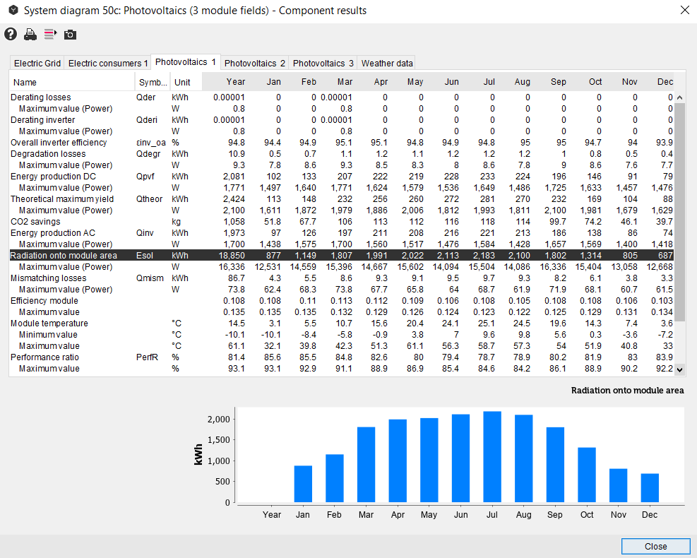
The main components of the grid-connected PV system in the system diagram are:
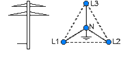
Electrical Grid
The electrical energy produced by the PV field is fed into the public electricity grid when ‘Feed-in’ is activated in the dialog window by clicking on the corresponding component.
Photovoltaic component: inverter and PV module field
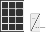
All parameters defined with the Wizard can be changed manually in the photovoltaic component. After all the changes have been entered, the validation through the Wizard must be carried out to ensure validity of the system.
Off-Grid PV Systems
For off-grid systems availability is very important, because insolation is not stable and does not always coincide with the load demand. In order to find the optimal system size costs and future demands have also be taken into consideration. The battery size has to be determined based on the acceptable availability of the system and local weather conditions. If needed, the generator has to be added as a back-up for PV system in order to increase its availability.
For off-grid systems the orientation has to be chosen for the “worst case scenario”, when the load to insolation ratio is the highest.
The size of PV array is determined based on required voltage and current in the system.
Off-grid PV systems can be designed the same way as grid-connected systems using the Wizard or manually, however in this case there shall be no feed-in into the electrical grid. These changes can be implemented in the dialog window of the electrical grid.
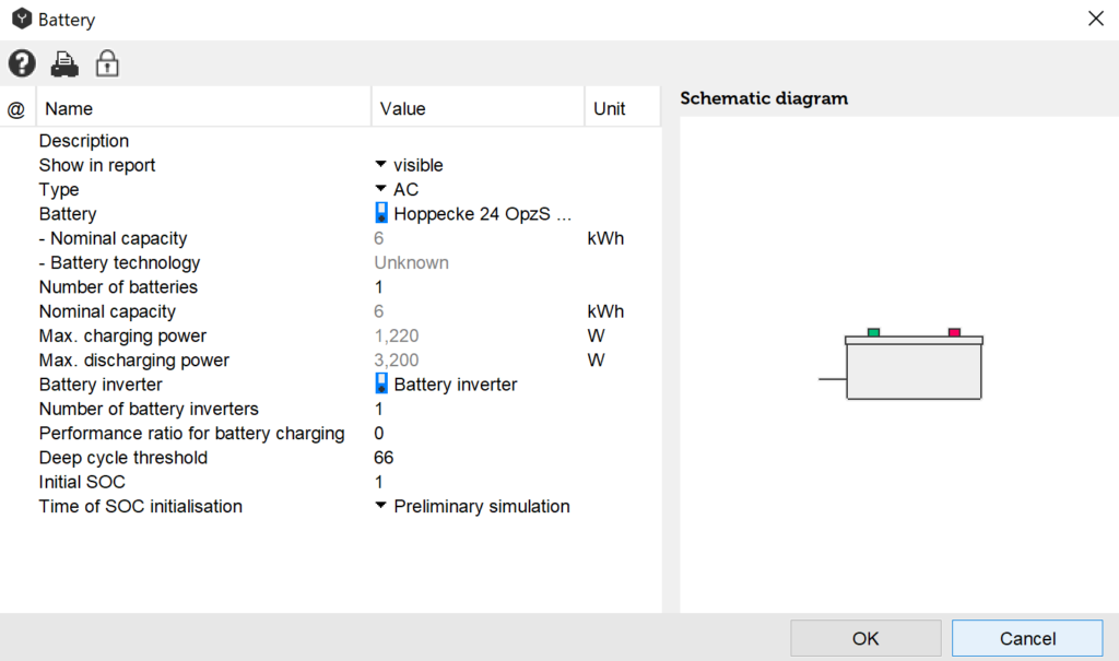
The battery is another important system component for off-grid systems, which is described in detail in chapter Batteries.
Sorting of Inverter Layouts
This feature allows the user to configure the sorting of inverter layouts according to specific requirements. This feature can be found in the ‘Settings’ under the tab ‘Advanced 2’. First, the criteria must be chosen for calculating the inverter layout, which are as follows:
Table: Inverter layout concepts
| Concept | Description |
| Microinverters | 1 inverter per module |
| String inverters | 1 string per MPP-tracker. No parallel strings are allowed. |
| Central inverters | At least 2 parallel strings per MPP-tracker. |
| Mixed | Allow mixing different inverter types in one layout variant. |
| Uniform | 1 type per layout variant (microinverters, string inverters, central inverters). Do not allow the combination of different concepts. |
Second, the sorting criteria must be chosen. The sorting criteria are taken into account sequentially in the ascending order from 1 to 4. The following criteria are available:
- Number of combinations, ascending;
- Total number of inverters, ascending;
- Total number of strings, ascending;
- MPP voltage, descending;
- Relative MPP voltage, descending;
- Nominal voltage deviation, ascending;
- Power ratio deviation, ascending.
The most important parameters are:
- Number of combinations, ascending;
- MPP voltage, descending;
- Total number of inverters, ascending
If there are too many results available after sorting, only the first 20 results are presented to the user.
Video: Simulation of east-west module fields