Variable Speed Pump Controller
The variable-speed pump controller is a two-channel controller regulating status and flow rate of the pump of the fresh-water station.
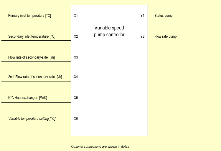
The controller has 4 (plus 2 optional) analogic inputs.
The controller has 2 digital and analogic outputs.
Block Diagram
The block diagram shows the employed measuring and controlling values
Controller Input Mask “Fixed Temperature Setting“
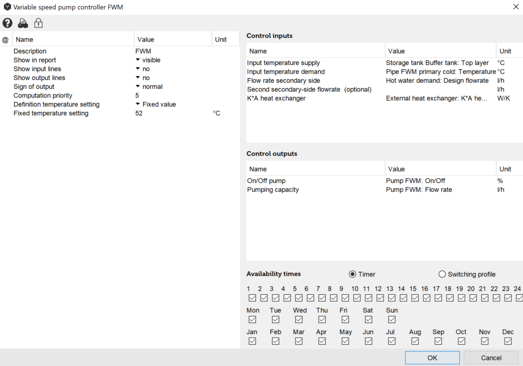
With this setting the pump of the fresh-water station cuts in as soon as hot water is tapped. Pump speed is adjusted so that the output temperature on the secondary-side can reach 52°C.
Controller Input Mask ”Variable Temperature Setting“

With this setting the pump of the fresh-water station cuts in as soon as hot water is tapped. Pump speed is adjusted so that the output temperature on the secondary-side is as high as the hot water demand temperature setting plus 5°C.
Input Values
Inlet Temperature of Primary Side [°C]
The value shows the point where the inlet temperature of the primary side is measured. Enter pipe temperature immediately before the plate heat exchanger or, e.g., the temperature of the tank connection.
Inlet Temperature of Secondary Side [°C]
The value shows the point where the inlet temperature of the secondary side is measured. Enter cold water temperature or pipe temperature immediately before the plate heat exchanger of secondary side.
Flow Rate of Secondary Side [l/h]
The value refers to the flow rate of the reference side. In fresh-water modules the value refers to the nominal flow rate of hot water withdrawal.
Second Flow Rate of Secondary Side [l/h]
As in flow rate of secondary-side a second flow rate may be entered. In case of the fresh-water station with circulation it is the circulation flow rate.
K*A Plate Heat Exchanger [W/K]
This value refers to the heat transfer properties and the heat transfer surface of the heat exchanger. Data are defined by the manufacturer.
Variable Temperature Setting [°C] (Optional)
The temperature that should be reached at the outflow of the plate heat exchanger, e.g. the temperature setting of the hot water demand.
Description of Control Parameters
Description
The “description“ value enables the user to assign controllers any name of number. Polysun assigns a consecutive number as a standard feature as different controllers are added chronologically in the hydraulic system.
Sign of Output
The term “Normal“ means that digital output signals are controlled as intended in the switching logics. (Example: if X3+X4>0 the output of pump 1 is positive)
The term “Inverted” that the digital output signals are multiplied -1.
Definition of Temperature Setting
- Fixed temperature setting
The components connected to the controller are adjusted so that the entered fixed temperature setting can be reached at the output of the plate heat exchanger on the secondary side. - Variable temperature setting
The components connected to the controller are adjusted so that the entered variable temperature setting can be reached at the output of the plate heat exchanger on the secondary side allowing for the relevant temperature shift.
Definition of Temperature Shift
- For example. 5 [K]
The temperature shift value enables to adjust temperature drops in the plate heat exchanger and pipe cooling after the plate heat exchanger. If the value is positive the outflow temperature will be increased by this value. If the value is negative the outflow temperature will be decreased by this value.
Output Values
Pump Status [%]
This digital output refers to the pump to be controlled, e.g. the pump of the fresh-water station. Select the relevant pump from the list.
Pump Flow Rate [l/h]
This analogic output adjusts the pump flow rate so that the desired temperature level can be reached on the secondary side of the plate heat exchanger. In the process the plate heat exchanger shows a temperature drop from the primary to the secondary side. This temperature drop may be corrected through the temperature shift.
The output is active only if the option “Flow rate setting” has been selected in the field “Flow rate controlled” for the pump to be controlled; otherwise pump settings will have priority over the analogic control outputs. Double click on the pump to change/check the settings.
Select the relevant pump from the list.
Overview of Control-Dependencies
Table: Control-dependencies of the fixed and variable temperature settings
| Outputs | Parameter | Tip | Inputs | Function |
| Y1: Pump Status Y2: Pump flow rate | Fixed temperature setting | Adjust pump to – Flow rate settings – | X1: Primary-side inlet temperature [°C] | Y1=0 if X3 + X4 = 0 Y1=1 if X3 + X4 > 0 Y2= f(X1, X2, X3 + X4, X5) |
| X2: Secondary-side inlet temperature [°C] | ||||
| X3: Secondary-side flow rate [l/h] | ||||
| X4: Second flow rate of secondary-side [l/h] | ||||
| X5: K*A Plate heat exchanger[W/K] | ||||
| Y1: Pump Status Y2: Pump flow rate | Variable temperature setting | Adjust pump to – Flow rate settings – | X1: Primary-side inlet temperature [°C] | Y1=0 if X3 + X4 = 0 Y1=1 if X3 + X4 > 0 Y2= f(X1, X2, X3 + X4, X5, X6) |
| X2: Secondary-side inlet temperature [°C] | ||||
| X3: Secondary-side flow rate [l/h] | ||||
| X4: Second flow rate of secondary-side [l/h] | ||||
| X5: Variable temperature setting [°C] | ||||
| X6: K*A Plate heat exchanger [W/K] |