Polysun Main Window (Graphical User Interface)
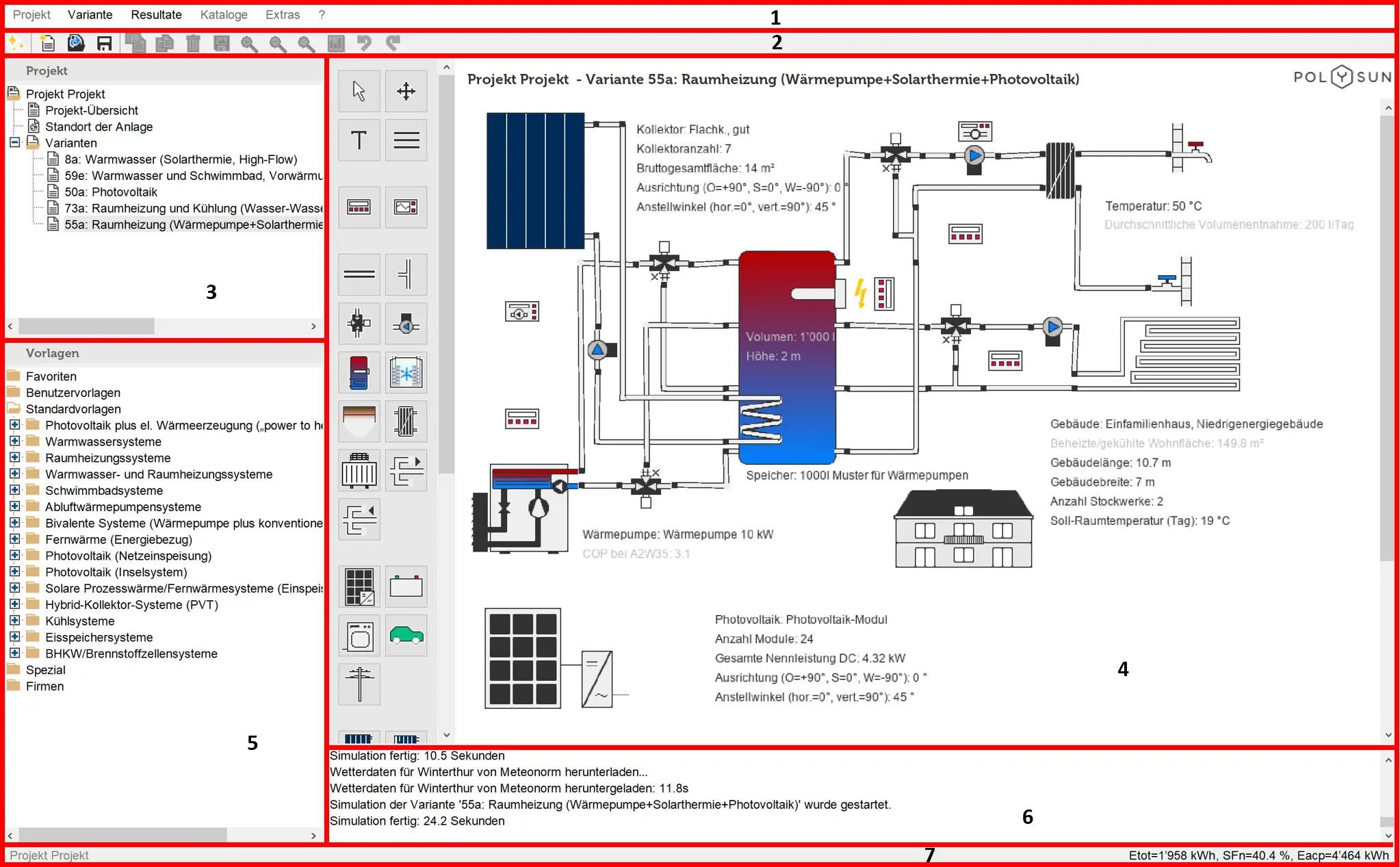
Polysun’s graphical user interface is essentially divided into three parts: on the top left are the project data, on the bottom left is the template collection; the working area is on the right-hand side. The parting lines between the above areas can be easily moved using your mouse so that the main window can be adjusted to fit the needs of all users.

- Menu bar
- Toolbar
- Project data (folder tree)
- Working area
- Template collection
- Console (status window)
- Status bar
Project Overview
Photograph of Property
Right-clicking on the field in the top left corner you will call-up the “Load photograph of property” command. Confirm with the left mouse-button to upload external photographs available in *.jpg, *.gif or *.png format. To delete a picture from the project overview right-click on it and select “Remove photograph”.
Comments on the Project
Here you will be able to enter comments that are of some interest for the relevant project.
System Diagrams
This field contains a list of the system diagrams you already created. Selecting a system diagram (highlighted in blue) the comments you entered on the system diagram appear in the field on the bottom right. These can be edited from the System diagram menu (Comment on the system diagram).
Location
A location may be either selected from the database or found on ”openstreetmaps.com”. This will require an active Internet connection.
Weather Data
By clicking on “from location”, the weather data referring to the selected location will be calculated according to Meteotest.
By clicking on “from file“, the data of a file will be extracted together with hourly values saved in the application folder of the Polysun installation. For further information please open the catalog “Profile”.
Tip: by typing in the first letter of the desired location name in the location selection list the software will automatically go to the first location name starting with the typed in letter. Typing then the remaining letters of the name the software will search for the location name that comes closest to the entered sequence.
Horizon
Use the slide controls to display a graphical representation of the position of the sun for the selected location for every hour and day of the year. The yellow curve represents the solar ecliptic on the selected day. The red line is the horizon that can be drawn in the chart by clicking the graph or entering the exact horizon points.
Tip: multiple values (separated by a semi-colon) may be added from the clipboard directly to the table using the Ctrl-C buttons.
System Diagrams
Here a list is displayed of all project system diagrams. The system diagram currently selected will be displayed in the working area. For further details on how to create system diagrams see chapter System diagram.
Templates
Polysun’s template collection is shown in the main window’s bottom left portion. Depending on the user level not all templates are available.
A template is a system scheme that becomes a system diagram and may be therefore simulated only after being copied to a project.
Templates are divided into three main groups (Vela Solaris, Special, Companies), consecutively numbered and sorted by category. Dragging your mouse over the list you will get a preview of the available system schemes. Templates may be directly selected off the list and copied to a project. Clicking them and confirming the related message (see also chapter Add template to project).
Tip: use the wizard to make your search for the desired template easier.
Working Area
The working area takes up the largest part of the main window. The working area includes the Project overview, the location page as well as the system schemes of templates and system diagrams.
System Schemes
A system scheme displays all components of a system. In Polysun all components of a system diagram may be clicked on:
- Select a component by simply clicking on it; four dots appear around the component to confirm the selection (see also Working with the Designer);
- Double-click to open the respective component dialogue box.
Attention: only components with a system diagram may be opened. Clicking on a template the user will be asked whether the template should be added to the project.
Component/Controller Dialogue Boxes
Dialogue boxes are the input windows displayed when the components of a system diagram are double-clicked. Dialogue boxes allow the user to:
- Adjust component-related settings;
- Open catalogs and possibly use other catalog entries or create new catalog entries for the respective components. The
 symbol refers to a catalog. Double-click on the catalog entry appearing next to it to open the relevant catalog.
 - Open a dropdown-menu. The
 symbol refers to a dropdown-menu: click on the name appearing next to it to open the corresponding selection.
Double-click on a control to open a modified dialogue box. The above mentioned editing functions are available. A special time profile can also be loaded. To this end the availability times profile should be activated. Double-click on the profile name to open a catalog menu
In the User manual you will find comprehensive instructions on how to select the right settings in the different component dialogue boxes.
Speed Buttons
The following buttons appearing (from left to right) at the top of the window can be used as “quick links“ to call-up, the different features from the menu:
 Wizard
 New project
 Save project
 Open project
 Copy system diagram
 Rename system diagram
 Save schematic system diagram
 Delete system diagram
 Zoom schematic system diagram
 Preliminary simulation
Status Window
All simulation procedures are logged in the field appearing under the working area. The command Copy message area in the Options menu allows messages to be copied. The command Delete message areas in the Options menu allows al messages to be deleted.
Status Line
The status line is shown on the lower end of the window. As soon as the project is saved the file name is displayed on the left-hand side in black characters. After a change has been made the characters turn grey to show that the current project was not yet saved. If a system diagram was simulated the energy demand on the system is shown in black characters on the right-hand side. After a change has been made the characters turn grey to show that the value is no longer up-to-date and should be simulated again.
Polysun Component Symbol Bar (Designer Only)
In the Designer version a vertical bar showing the symbols of all system components is displayed on the left-hand side of the working area. Dragging the mouse over the different symbols the respective component names will be shown.
Components can be placed in the working area as follows:
- Click on the desired component.
- Click on the design area in the working area. The desired component will be placed in the working area.
- Double-clicking on the component previously placed in the working area a dialogue box opens and the components can be edited.
For further details on how to create a system diagram see chapter Working with Designer.