Temperature Controller with AND/OR Operation
The temperature controller regulates the status of up to two components based on one or two temperature differences. The controller may be used for different components including the switching valve (see chapter Mixing valve controller)
The controller has 1 (plus 3 optional) analogic inputs.
The controller has 1 (plus 1 optional) digital outputs.
The switch cuts-in or off based on the comparison of two or four different temperatures. The comparison may be carried out with a constant value; if several temperature sensors are used the different measured temperatures will be compared with one another.
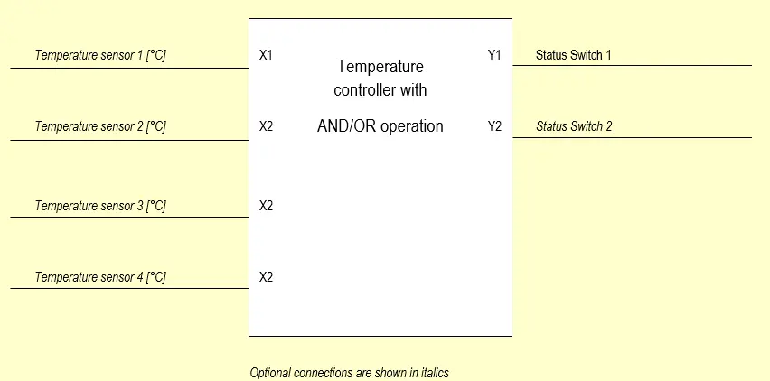
Block Diagram
The block diagram shows the employed measuring and controlling values
Controller Input Mask without Logical Connection Once with “Fixed Value” and Once with “Variable Value“
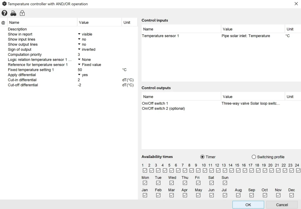
With this setting the output located on the three-way valve and marked with X opens as soon as the pipe’s solar inlet temperature is higher than 50°C plus 2°.

With this setting the outflow located on the three-way valve and marked with X opens as soon as the pipe’s solar inlet temperature is higher than the temperature on layer 8 plus 2°.
Controller Input Mask with Logical Connection Once with “Fixed Value” and Once with “Variable Value“
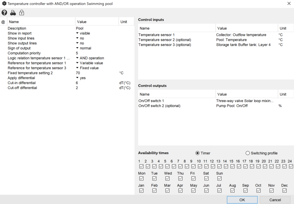
With this setting the swimming-pool pump is activated only if the temperature measured by Temperature sensor 1 (Collector: outflow temperature) is higher than the temperature measured by Temperature sensor 2 (Pool: temperature) AND the temperature measured by Temperature sensor 3 (Tank: Layer 4) is higher than the reference for Temperature sensor 3: Fixed value = 70°C. As the swimming-pool is only used from May through to September the timer will be set accordingly.
Input Values
Temperature Sensor 1 [°C]
The value refers to the point where the temperature should be measured. Enter a component from the list.
Temperature Sensor 2 [°C] (Optional)
The value refers to the point where the reference temperature for temperature sensor 1 should be measured. Enter a component from the list.
Temperature Sensor 3 [°C] (Optional)
In case of AND / OR operation an additional switching conditions may be defined. Analogous to Temperature sensor 1.
Temperature Sensor 4 [°C] (Optional)
The value refers to the point where the reference temperature for temperature sensor 3 should be measured. Enter a component from the list.
Description of Control-Parameters
Description
The “description” value enables the user to assign controllers any name of number. Polysun assigns a consecutive number as a standard feature as different controllers are added chronologically in the hydraulic system
Sign of the Output
The term “Normal“ means that digital output signals are controlled as intended in the switching logics. (Example: if X1>Fixed value or if X1>X2 the output Status Switch 1 is positive). The term “Inverted” means that the digital output signals are multiplied by -1. (Example: if X1>X2 the output Switch 1 is equal to zero). In case of inverted selection hysteresis may not be used.
Logical Connection Temperature Sensor 1 and 3
- None
The output is activated based on the requirements existing amongst “Temperature sensor 1, Reference temperature, Temperature sensor 2 or Fixed temperature setting 1“. - AND-Operation
The requirements existing between “Temperature sensor 1, 2, Fixed temperature setting 1“, AND “Temperature sensor 3, 4, Fixed temperature setting 2“ must be met. - OR-Operation
The requirements existing between “Temperature sensor 1, 2, Fixed temperature setting 1“, OR “Temperature sensor 3, 4, Fixed temperature setting 2“ must be met.
Definition of Temperature Setting
- Fixed value
If the temperature measured by Temperature sensor 1 or 3 drops below the specified Fixed temperature setting 1 or 2, the controller output switches to “on”. - Variable value
If the temperature measured by Temperature sensor 1 or 3 exceeds the temperature measured by Temperature sensor 2 or 4, the controller output switches to ”on“.
Use of Hysteresis
If hysteresis is used the following applies
- Cut-in hysteresis [K]
If the temperature measured by Temperature sensor 1 or 3 exceeds the reference temperature by the specified temperature hysteresis, the controller output switches to ”on“. - Cut-off hysteresis [K]
If the temperature measured by Temperature sensor 1 or 3 drops below the reference value by the specified temperature hysteresis, the controller output switches to ”off“.
Output Values
Status Switch 1
This digital output refers to the component to be controlled within the system. Select the relevant component from the list.
Status Switch 2 (Optional)
This digital output is activated just like the Status Switch 1 output. Select the relevant component from the list.
Overview of Control-Dependencies
Table: Control-dependencies of the temperature controller with AND/OR operation
| Outputs | Parameter | Tip | Inputs | Function | |
| Y1: Status Switch 1 Y1 = Y2 Y2: Status Switch 2 | No operation Fixed value | If hysteresis is applied alter cut-in and off temperatures | X1: Temperature sensor 1 | Y1=0 if X1 < Fixed temperature setting 1 [°C] | |
| Y1=1 if X1 > Fixed temperature setting 1 [°C] | |||||
| Y1=1 if X1 > Fixed temperature setting 1 [°C] + Cut-in-Hyst. Y1=0 if X1 < Fixed temperature setting 1 [°C] + Cut-off-Hyst. | |||||
| Y1: Status Switch 1 Y1 = Y2 Y2: Status Switch 2 | No operation Variable value | If hysteresis is applied alter cut-in and off temperatures | X1: Temperature sensor 1 X2: Temperature sensor 2 | Y1=0 if X1 < X2 | |
| Y1=1 if X1 > X2 | |||||
| Y1=1 if X1 > X2 + Cut-in temperature difference [K] Y1=0 if X1 < X2 + Cut-off temperature difference [K] | |||||
| Y1: Status Switch 1 Y1 = Y2 Y2: Status Switch 2 | AND-Operation | Both Temperature sensor 1 and 3 may be compared either with Fixed temperature settings 1 and 2 or with temperature sensors 2 and 4 | X1: Temperature sensor 1 X2: Temperature sensor 2 X3: Temperature sensor 3 X4: Temperature sensor 4 | Y1=0 if | X1 < X2 or X1 < Fixed temperature setting 1 [°C] AND X3 < X4 or X3 < Fixed temperature setting 2 [°C] |
| Y1=1 if | X1 > X2 or X1 > Fixed temperature setting 1 [°C] AND X3 > X4 or X3 > Fixed temperature setting 2 [°C] | ||||
| Hysteresis analogous to “No Operation“ | |||||
| Y1: Status Switch 1 Y1 = Y2 Y2: Status Switch 2 | OR-Operation | Both Temperature sensor 1 and 3 may be compared either with Fixed temperature settings 1 and 2 or with temperature sensors 2 and 4 | X1: Temperature sensor 1 X2: Temperature sensor 2 X3: Temperature sensor 3 X4: Temperature sensor 4 | Y1=0 if | X1 < X2 or X1 < Fixed temperature setting 1 [°C] OR X3 < X4 or X3 < Fixed temperature setting 2 [°C] |
| Y1=1 if | X1 > X2 or X1 > Fixed temperature setting 1 [°C] OR X3 > X4 or X3 > Fixed temperature setting 2 [°C] | ||||
| Hysteresis analogous to “No Operation“ | |||||